alanlan86
- 2025-01-24
-
回复了主题帖: 回帖赢好礼 | 关于无线技术的那些事儿
针对蓝牙技术本身,还有很多可以深挖的话题和技术细节点~~~
- 2025-01-01
-
回复了主题帖: 【Follow me第二季第4期】PB03蓝牙模块+小程序体验
wangerxian 发表于 2024-12-23 09:39 如果想要自己编程这个芯片的话,和ESP32相比复杂吗? 如果是简单的BLE数传的话,还算简单!(前提是对BLE协议的一些基本概念,需要有) 复杂的应用暂时没有试验!
- 2024-12-22
-
发表了主题帖: 【Follow me第二季第4期】RP2350-Pico2试玩体验
本帖最后由 alanlan86 于 2024-12-22 12:24 编辑 # 【Follow me第二季第4期】RP2350-Pico2试玩  - 顺着2024 2Q4的Follow Me购置了一块Pico2的板子,在Arduino Nano Connect上有上手RP2040,对于Arduino IDE有一个了解。此前Pico /Pico W系列有用MicroPython进行过简单调试。 - 因此考虑RP2350上试一下其他IDE进行开发调试。之前的WSL上直接编译C/C++ SDK也有尝试,总体还是感觉没有VSCode+扩展Extension来得方便~~~ 不过,搭建环境中间还是遇到了一点点问题,后面会具体讲到! ## RP2350 Pico2简介 ### RP2350 的功能特性 RP2350 是一款强大的微控制器,具有以下关键特性: 1. 双核架构:RP2350 搭载了双核 Arm Cortex-M33 处理器或 Hazard3 RISC-V 处理器,运行频率高达 150 MHz,性能远超 RP2040。 2. 丰富的内存:它拥有 520 kB 的片上 SRAM,分为 10 个独立的存储区,并支持通过专用 QSPI 总线连接高达 16 MB 的外部 QSPI 闪存/PSRAM,此外还可通过可选的第二个芯片选择连接额外的 16 MB 闪存/PSRAM。 3. 多功能外设:RP2350 集成了丰富的外设,包括 2 个 UART、2 个 SPI 控制器、2 个 I2C 控制器、24 个 PWM 通道、支持主机和设备模式的 USB 1.1 控制器和 PHY、12 个 PIO 状态机以及 1 个 HSTX 外设。 4. 片上电源管理:它内置了开关模式电源,可生成内核电压。 5. 灵活的封装选项:RP2350 提供 QFN-80 (10 × 10 mm) 和 QFN-60 (7 × 7 mm) 两种封装选择,并有带和不带封装内闪存的版本。 ### 与 RP2040 的比较 与上一代 RP2040 相比,RP2350 具有以下优势: 1. 更高的时钟频率:RP2350 的时钟频率为 150 MHz,而 RP2040 为 133 MHz。 2. 更多的引脚和 GPIO:RP2350 B 型号具有 80 个引脚和 48 个 GPIO,而 RP2040 只有 40 个引脚和 26 个 GPIO。 3. 更大的内存容量:RP2350 集成了 520 KB 的 SRAM,而 RP2040 只有 264 KB。 此外,RP2354 型号还内置了 2 MB 闪存,而 RP2040 则需要外部闪存芯片。 4. 更多的模拟输入:RP2350 B 型号具有 8 个模拟输入,而 RP2040 和 RP2350 A 型号只有 4 个。 5. 更强大的内核:RP2350 采用了 Arm Cortex-M33 内核,它基于 Armv8-M 架构,支持硬件除法和更多 32 位指令,性能和功耗都优于 RP2040 的 Arm Cortex-M0+ 内核。 6. 增强的安全性:Cortex-M33 内核增强了安全性,更适合物联网应用。 ## 环境搭建 - 环境搭建整体参考微雪的文档:[本地安装方式](https://www.waveshare.net/wiki/RP2350-Plus#C.2FC.2B.2B.E7.B3.BB.E5.88.97 "本地安装方式") - 以下我才用在线网络download工具链和SDK的方式,中间出现的raspberry pico setup 失败的问题。 ### VSCode安装 - 本身我的电脑上调试其他代码有把VSCode安装好,因此没有重新下载。若您的电脑未有这个软件,可以官网下载和安装,无其他特殊的设置或者要求! - 在Extension中选择扩展插件Raspberry Pi Pico进行安装。 安装完成后,在左侧的可看到rasoberry pi pico project的图标。 - 可以在General 菜单下->New Project From Example创建一个Blink的例程。 - 点击creat按钮后,如果网络不行的时候,就会提示setup fail的消息提示! - 此时,可以进入C:\Users\用户\的路径下,看到“.pico-sdk”文件夹。文件夹内的代码仓库应该没有从GitHub上拉取上网。在我的电脑上,用了科学上网也没法拉取成功,可采用手动方式git将sdk的代码仓库拉取【早上7点GitHub拉取一般会比较顺畅!】。 - 然后,重新import example或者creat example都可以了! ### 调试 - build编译通过后,可以将uf2文件拷贝到RP2350 Pico2,可以观察到LED闪灯。 - 至此,这个环境就可以了!接着,可以用Pico2配合之前Pico的扩展底板,用C/C++熟悉的环境,进行其他外设的调试了!
- 2024-12-20
-
发表了主题帖: 【Follow me第二季第4期】PB03蓝牙模块+小程序体验
本帖最后由 alanlan86 于 2024-12-21 10:26 编辑 # 【Follow me第二季第4期】PB03蓝牙模块+小程序体验 ## 简介 - 最近刚好需要用到蓝牙和小程序调试应用,因此顺着这个2024 2Q4 Follow Me在digikey平台上购买了PB03的蓝牙模块。 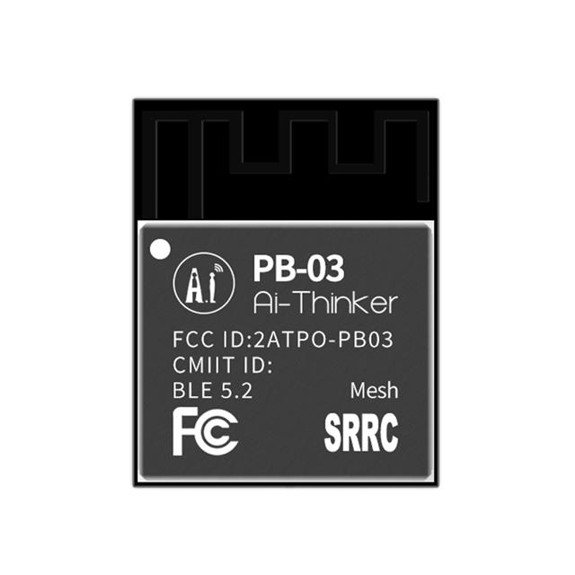 - 购买模块链接:[PB03模块在Digikey购买入口](https://www.digikey.cn/zh/products/detail/ai-thinker/PB-03/16688850 "PB03模块在Digikey购买入口") ### PB03模块: - 最高支持 BLE 5.2 协议,支持Sig Mesh,支持天猫精灵/APP语音控制,支持亚马逊 Alexa Echo 音响控制。 - 支持半孔焊盘和天线孔和板载天线。半孔焊盘可把天线引导主板上,天线孔可在模组上直接焊接弹簧天线; - 亮度(占空比)调整范围 5%-100%,PWM 输出频率 1KHz; - 支持ESP32-G蓝牙网关通讯,实现远程随时随地控制; - 支持windows环境SDK二次开发,资料代码全部开源,支持AT指令接入天猫精灵; - 支持Android/iOS APP和微信小程序控制;  - 链接进入厂家官方网站,获取响应的文档资料: [文档资料](https://docs.ai-thinker.com/blue_tooth_pb "文档资料") ------------ ## 原理图 - PB03 Kit的原理图(如下的官方的pdf文档截图,估计是模组兼容该公司的ESP32-C3模组,因此看到原理图标注仍然是ESP32-C3的模组引脚定义~~~ 汗!凑合着看吧~~~) - 板子主要就是PHY6252 PHY+的BLE芯片制造的BLE模组,外围就是一个USB转串口+LED灯+LDO。 ## AT命令测试 ### 固件 - 模组在出厂已经烧录的AT命令固件,若需要二次开发或者重新烧录固件,都可以从官方资料链接中获取到。 - 从下载AT指令固件位置解压得到《Combo模组通用指令_V1.3.0.docx》AT指令集。 ### 串口AT命令测试 - AT+HELP也可以查询到模组当前固件支持的指令列表。 ## 小程序 - 接着,就是我此次重点关注的小程序部分,可以通过官网链接到Github找到参考的小程序代码。 [微信小程序源码](https://github.com/Ai-Thinker-Open/AiPBxxForWeChat "微信小程序源码") - 拉取代码,然后安装好微信小程序的开发工具,即可以调试。缺省默认的js代码,有一个过滤名称不匹配的问题,需要做一个调整。 ### 无法显示搜索设备问题 - 检查debug log信息可见设备可以被搜索到,但是没有显示在界面上。 ### 搜索设备 - 调整匹配名字'ai-thinker',可搜索到设备。 ### 链接和通信 ## 官方代码问题 - 在扫描过滤BLE广播设备名称时,'ai-thinker'名称需要修改为小写,因为开发板默认广播名字的'ai-Thinker'大写。或者通过AT命令修改蓝牙广播名字也是一种解决方式。 ```json wx.onBluetoothDeviceFound(function(devices) { //剔除重复设备,过滤名字是否为 Ai-Thinker var isnotexist = true if (devices.deviceId) { if (devices.advertisData) { devices.advertisData = app.buf2hex(devices.advertisData) } else { devices.advertisData = '' } console.log(devices) for (var i = 0; i < that.data.devicesList.length; i++) { if (devices.deviceId == that.data.devicesList.deviceId) { isnotexist = false } } if (isnotexist && devices[0].name === 'ai-thinker') { that.data.devicesList.push(devices[0]) } } else if (devices.devices) { if (devices.devices[0].advertisData) { devices.devices[0].advertisData = app.buf2hex(devices.devices[0].advertisData) } else { devices.devices[0].advertisData = '' } console.log(devices.devices[0]) for (var i = 0; i < that.data.devicesList.length; i++) { if (devices.devices[0].deviceId == that.data.devicesList.deviceId) { isnotexist = false } } if (isnotexist && devices.devices[0].name === 'ai-thinker') { that.data.devicesList.push(devices.devices[0]) } } else if (devices[0]) { if (devices[0].advertisData) { devices[0].advertisData = app.buf2hex(devices[0].advertisData) } else { devices[0].advertisData = '' } console.log(devices[0]) for (var i = 0; i < devices_list.length; i++) { if (devices[0].deviceId == that.data.devicesList.deviceId) { isnotexist = false } } if (isnotexist && devices[0].name === 'ai-thinker') { that.data.devicesList.push(devices[0]) } } that.setData({ devicesList: that.data.devicesList }) }) }, ``` ## 总结 - AT命令透传的命令蓝牙模组就是纯粹的数据通道。小程序打开蓝牙适配器,将设备搜索到后,将Service和Characteristic打通,数据透传就比较简单了。 - 原理图和小程序的两处“小虫子”,大家在试玩时候,需要留意哦!!!~~~
- 2024-12-08
-
发表了主题帖: 【Follow me第二季第4期】任务汇总
本帖最后由 alanlan86 于 2025-1-13 09:47 编辑 # 开发板_Arduino Nano RP2040 Connect ## 汇总介绍视频 [localvideo]cdfc66f8d556d386e9bcdf8997841373[/localvideo] 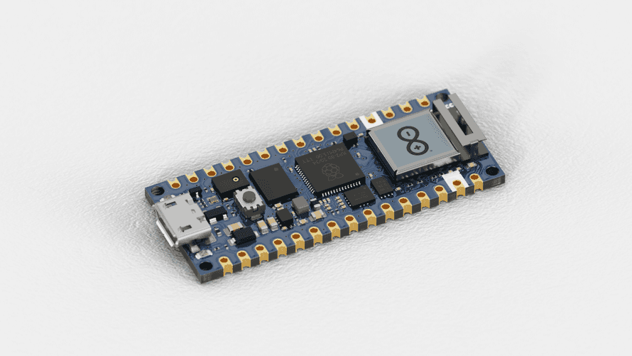 本期的Follow Me活动的实验,大部分都可以参考官方的示例教程实现: [Arduino Nano RP2040 Connect 官方的教程](https://docs.arduino.cc/tutorials/nano-rp2040-connect/rp2040-01-technical-reference/ "Arduino Nano RP2040 Connect 官方的教程") # 硬件 关于Nano RP2040 Connect的原理图,可以通过如下链接获取: [Nano RP2040的原理图](https://docs.arduino.cc/hardware/nano-rp2040-connect/ "Nano RP2040的原理图") ## RGB三色灯 - 板载RGB三色彩灯,分别链接了NINA-W102的LED R/G/B引脚上,RP2040通过I2C和SPI和NINA-W102进行连接和通信。 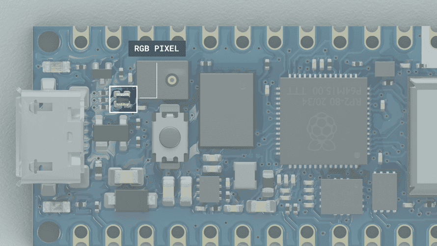 ## IMU 6轴Motion Sensor - 本次任务二用到板载的ST 6轴传感器 LSM6DSOXTR,它内置IMU计算单元、3轴的陀螺仪、3轴加速度以及测温传感器(用于温度补偿等)。 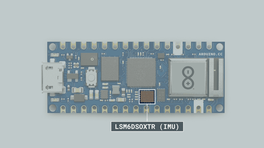 ## 麦克风 - 板载一颗MP34DT05数字麦克风,通过PDM接口和RP2040进行链接。 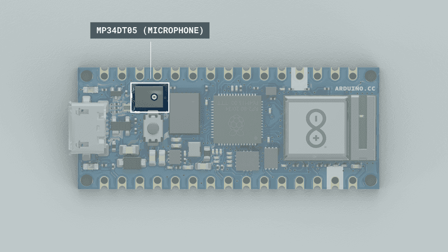 # 软件 ## 任务一 搭建环境 - 要求:搭建环境并开启第一步Blink三色LED / 串口打印Hello DigiKey & EEWorld!; ## 步骤 - (1)从https://www.arduino.cc/ 官网下载Arduino的IDE安装包,一路进行Next下一步即可完整安装完成整个开发环境。 - (2)软件库的更新部分,最好有科学上网支持,否则拉取某些库会比较慢。 - (3)更新一下NINA的固件。 - (4)编译运行第一个程序,upload成功就可以看到点灯blinky效果了。 ## 流程图 ## 源代码 - 将第一个任务的Blinky点灯以及第二个任务IMU读取sensor数据整合在一起。 ```cpp #include "WiFiNINA.h" #include float Ax, Ay, Az; float Gx, Gy, Gz; uint32_t cycle = 0; void setup() { // put your setup code here, to run once: Serial.begin(9600); Serial.println("Arduino Nano RP2040 Connect Startup..."); Serial.println("Hello Digikey&EEWorld!"); while(!Serial); if (!IMU.begin()) { Serial.println("Failed to initialize IMU!"); while (1); } Serial.print("Accelerometer sample rate = "); Serial.print(IMU.accelerationSampleRate()); Serial.println("Hz"); Serial.println(); Serial.print("Gyroscope sample rate = "); Serial.print(IMU.gyroscopeSampleRate()); Serial.println("Hz"); Serial.println(); pinMode(LEDR, OUTPUT); pinMode(LEDG, OUTPUT); pinMode(LEDB, OUTPUT); } void loop() { char message[32]; // put your main code here, to run repeatedly: snprintf(message, sizeof(message), "cycle=%d, run...", cycle++); Serial.println(message); if (IMU.accelerationAvailable()) { IMU.readAcceleration(Ax, Ay, Az); Serial.println("Accelerometer data: "); Serial.print(Ax); Serial.print('\t'); Serial.print(Ay); Serial.print('\t'); Serial.println(Az); Serial.println(); } if (IMU.gyroscopeAvailable()) { IMU.readGyroscope(Gx, Gy, Gz); Serial.println("Gyroscope data: "); Serial.print(Gx); Serial.print('\t'); Serial.print(Gy); Serial.print('\t'); Serial.println(Gz); Serial.println(); } digitalWrite(LEDR, HIGH); digitalWrite(LEDG, HIGH); digitalWrite(LEDB, HIGH); delay(1000); digitalWrite(LEDR, LOW); digitalWrite(LEDG, LOW); digitalWrite(LEDB, LOW); delay(1000); } ``` ## 任务二 IMU传感器 - 要求:学习IMU基础知识,调试IMU传感器,通过串口打印六轴原始数据; ### 流程图 ### 源代码 - 整合#include LSM6DS的库,然后在setup调用初始化传感器,并将加速度和陀螺仪的sample rate打印出来。 ```cpp if (!IMU.begin()) { Serial.println("Failed to initialize IMU!"); while (1); } Serial.print("Accelerometer sample rate = "); Serial.print(IMU.accelerationSampleRate()); Serial.println("Hz"); Serial.println(); Serial.print("Gyroscope sample rate = "); Serial.print(IMU.gyroscopeSampleRate()); Serial.println("Hz"); Serial.println(); ``` - 在loop循环部分读取sensor的6轴数据值。 ```cpp if (IMU.accelerationAvailable()) { IMU.readAcceleration(Ax, Ay, Az); Serial.println("Accelerometer data: "); Serial.print(Ax); Serial.print('\t'); Serial.print(Ay); Serial.print('\t'); Serial.println(Az); Serial.println(); } if (IMU.gyroscopeAvailable()) { IMU.readGyroscope(Gx, Gy, Gz); Serial.println("Gyroscope data: "); Serial.print(Gx); Serial.print('\t'); Serial.print(Gy); Serial.print('\t'); Serial.println(Gz); Serial.println(); } ``` ### 测试 - upload代码后,可以通过Serial Monitor观察到Sensor的数值。 ## 任务三 麦克风 - 要求:学习PDM麦克风技术知识,调试PDM麦克风,通过串口打印收音数据和音频波形。 ### 流程图 ### 源代码 ```cpp /* This example reads audio data from the on-board PDM microphones, and prints out the samples to the Serial console. The Serial Plotter built into the Arduino IDE can be used to plot the audio data (Tools -> Serial Plotter) Circuit: - Arduino Nano 33 BLE board, or - Arduino Nano RP2040 Connect, or - Arduino Portenta H7 board plus Portenta Vision Shield, or - Arduino Nicla Vision This example code is in the public domain. */ #include // default number of output channels static const char channels = 1; // default PCM output frequency static const int frequency = 16000; // Buffer to read samples into, each sample is 16-bits short sampleBuffer[512]; // Number of audio samples read volatile int samplesRead; void setup() { Serial.begin(9600); while (!Serial); // Configure the data receive callback PDM.onReceive(onPDMdata); // Optionally set the gain // Defaults to 20 on the BLE Sense and 24 on the Portenta Vision Shield // PDM.setGain(30); // Initialize PDM with: // - one channel (mono mode) // - a 16 kHz sample rate for the Arduino Nano 33 BLE Sense // - a 32 kHz or 64 kHz sample rate for the Arduino Portenta Vision Shield if (!PDM.begin(channels, frequency)) { Serial.println("Failed to start PDM!"); while (1); } } void loop() { // Wait for samples to be read if (samplesRead) { // Print samples to the serial monitor or plotter for (int i = 0; i < samplesRead; i++) { if(channels == 2) { Serial.print("L:"); Serial.print(sampleBuffer); Serial.print(" R:"); i++; } Serial.println(sampleBuffer); } // Clear the read count samplesRead = 0; } } /** * Callback function to process the data from the PDM microphone. * NOTE: This callback is executed as part of an ISR. * Therefore using `Serial` to print messages inside this function isn't supported. * */ void onPDMdata() { // Query the number of available bytes int bytesAvailable = PDM.available(); // Read into the sample buffer PDM.read(sampleBuffer, bytesAvailable); // 16-bit, 2 bytes per sample samplesRead = bytesAvailable / 2; } ``` ## 测试 - 下载固件可以通过Serial Monitor可看到麦克风的数值,且可以绘制出曲线。 # 演示 ## 任务一和二的视频 [localvideo]0179e9700e228002860ffa565ff3d7af[/localvideo] ## 任务三的视频 [localvideo]aec56701d586177dc3456b74027084a1[/localvideo] # 综合汇总源代码 - 可下载源码汇总: # 活动心得及体验 - 本季活动的整体感觉比较之前的几期来说,任务难度偏容易一些~~~ 更多的技术学习会落在板子的自行扩展创意玩耍上。 - 期待下一次能够有AI+结合 相关的板子可以玩一玩~~~ 体验一下时下最热门的技术!
- 2024-12-07
-
发表了主题帖: 【Follow me第二季第1期】微型低压步进电机驱动芯片试用
# TMC2300板子 - 在今次的Follow Me活动中,顺手在Digikey上购买了一块TMC2300的步进电机驱动板子,它刚好可以用在我的一个小设计上。 ## 实物照片 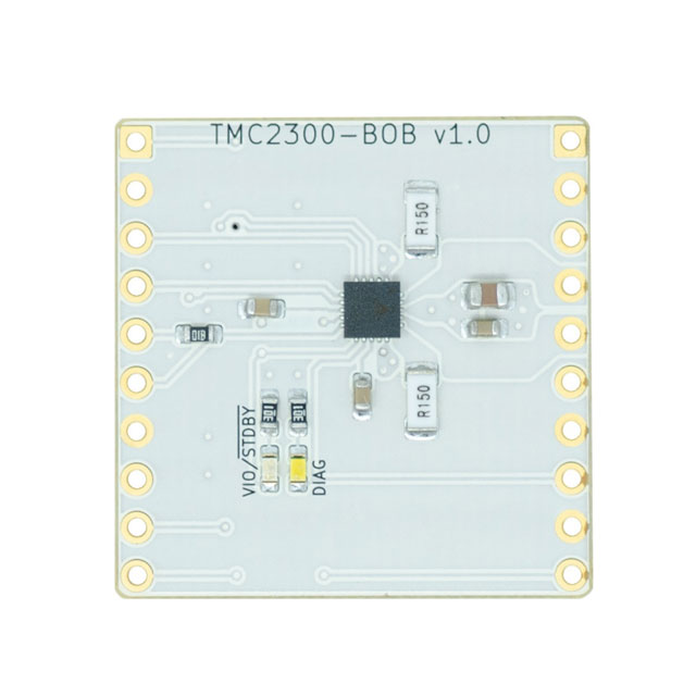 ## 购买链接 https://www.digikey.cn/zh/products/detail/analog-devices-inc-maxim-integrated/TMC2300-BOB/10490856 ## TMC2300简介 TMC2300是微型步进电机驱动芯片。该芯片特色功能有:超静音、抑共振、防堵转、电池供电超节能、内部集成功率MOS、体积小、精确、高效、可靠等,待机电流消耗小于1μA,该款驱动器改变了便携式设备和IoT中电机的使用方式。 **在我的应用中,因为是一个便携式的小设备,所以对于待机低功耗和超静音,电池供电这些点都刚好用到。** 常见的传统驱动芯片转动步进电机时,会出现人耳听得见的高音噪声或电机抖动的现象,严重影响产品的体验度。而TMC2300通过StealthChop静音技术, 可以使步进电机在运行时将噪音降低在10dB以下,达到超静音性能;还可以通过StallGuard4功能进行失速检测、堵转检测; 打开CoolStep功能让电机自适应负载,电机节能最高到90%。 ## 芯片内部框图  ## 板子的功能特性 - 2相步进电机驱动器 - 电流最高1.2A RMS (均方根电流) - 电池供电设备(至少2个AA / NiMh电池,或1-2个锂离子电池) - 电压范围为1.8V…11V DC - 待机电流消耗
- 2024-11-21
-
发表了主题帖: 【Follow Me第二季第4期】开箱帖
今天早上来了收到活动订购的3块板子~~~ 展示一下!接着,可以用之前pico W/pico 的底板把Pico 2玩一下 再来Arduino 玩一下Connect Nano, 最后,BLE耍一耍~~~
- 2024-11-12
-
加入了学习《【2024 DigiKey创意大赛】+智慧焊接工作台》,观看 智慧焊接工作台
-
发表了主题帖: 冲【Follow Me第二季第4期】已下单,等板子!!!!
选了这3款板子拼单!等待收到板子~~~~
- 2024-10-30
-
加入了学习《ESP32-S3-LVGL》,观看 自行车智能灯
-
加入了学习《ESP32-S3-LVGL》,观看 ESP32-S3-LCD-LVGL
-
发表了主题帖: 2024DigiKey创意大赛】【自行车智能灯】汇总提交
自行车智能灯 作者:alanlan86 一、作品简介 (1)作品照片 (2)简介 自行车智能车灯安装在自行车把手位置,能够根据光传感器自动点亮LED灯,用于做车头照明;能够根据IMU监测车把的左转右转动作,实现方向闪灯提醒;能够根据毫米波雷达探测前方是否有障碍物,发出警告提醒。 ESP32-S3-LCD-EV-Board做为主控板,外接光敏电阻传感器,通过ADC采集光的强度。通过I2C采集ICM-20948的姿态数据,进行车把方向监测。通过读取毫米波传感器的终端输出,监测前方是否有障碍物。 (3)物料清单 物料 型号 功能 1 ESP32-S3-LCD-EV-Board 主控、LCD显示交互、LED三色灯 2 ADAFRUIT TDK INVENSENSE ICM-20948 9轴传感器 3 MerryTek MC01-5G 毫米波传感器(集成光敏电阻) A、ESP32-S3-LCD-EV-Board ESP32-S3-LCD-EV-Board 是一款基于 ESP32-S3 芯片的屏幕交互开发板,通过搭配不同类型的 LCD 子板,可以驱动 IIC、SPI、8080 以及 RGB 接口的 LCD 显示屏。同时它还搭载双麦克风阵列,支持语音识别和近/远场语音唤醒,具有触摸屏交互和语音交互功能,满足用户对多种不同分辨率以及接口的触摸屏应用产品的开发需求。 目前从Digikey上采购到的开发板:搭配 480x480 LCD 的 ESP32-S3-LCD-EV-Board,有丰富的外设和强大的显示能力。 该款开发板核心模组型号ESP32-S3-WROOM-1-N16R16V, 该模组是一款通用型 Wi-Fi + 低功耗蓝牙 MCU 模组,搭载 ESP32-S3 系列芯片,内置 16 MB flash 以及 16 MB PSRAM。除具有丰富的外设接口外,模组还拥有强大的神经网络运算能力和信号处理能力,适用于 AIoT 领域的多种应用场景。 B、ICM-20948模组 ICM-20948是TDK(InvenSense)推出的9轴系列的9轴运动跟踪设备,专为电池供电的高性能消费电子产品设计。 9轴产品系列采用了经过市场验证的MotionFusion以及运行时校准,该校准由InvenSense市场的MPU-65xx系列产品支持。此解决方案已售出数百万台,并经过了市场验证。 9轴运动跟踪已成为包括智能手机、平板电脑和可穿戴设备在内的许多消费电子设备的关键功能。与离散解决方案相比,集成9轴设备的尺寸优势对于空间有限的产品(如智能手机和可穿戴传感器)来说是引人注目的。 InvenSense的9轴设备将3轴陀螺仪、3轴加速计和3轴指南针与车载数字运动处理器结合在一起(DMP) 能够处理复杂的运动融合算法。 C、MerryTek MC01-5G MC01-5G是一款5.8G微波感应模块,它支持5~12VDC宽输入电压,工作电流小,待机功耗低。 产品体积小,易于安装。 采用低阻抗专利天线技术,抗干扰能力强。 内置抗微风、细雨多重数字滤波器算法、稳定输出高低电平、PWM、UART等控制信号。 预留灵敏度,延时时间,光控阀值等参数设置脚位,功能设置灵活。 产品具有感应距离远、可内置、无死区、不受温湿度、噪音、灰尘、气流、环境光影响等优点。广泛 应用于感应灯具、自动门控制、智能家居、智能卫浴、小家电、安防、IOT、智能终端等产品,及走廊、 车库、洗手间、庭院、阳台等场所。 二、系统框图 主控模组 整个系统构成相对简单,采用ESP32-S3-WROOM-1-N16R16V模块作为主控,它是一款拥有2.4 GHz Wi Fi (802.11 b/g/n) + Bluetooth® 5 (LE)的无线高集成度模组,内置 ESP32 S3 系列芯片,Xtensa® 双核 32 位 LX7 处理器 Flash最大可选 16 MB,PSRAM最大大可选 8/16 MB,最多支持36个GPIO,丰富的外设 板上带PCB天线非常便利于集成化设计。开发板上有WS2812,三色LED灯,可用于做用户交互指示。 整个ESP32-S3-LCD-EV-Board开发板的功能框图如下所示: 板载带有的Audio部分,暂时未有使用到,后续可作为扩展使用。 传感器ICM20948 ICM20948是一款来自于TDK InvenSense推出的一款9轴运动检测传感器,它与主控板模块连接比较简单,采用I2C方式进行通信,支持400K Hz通信速率。 MC01-5G微波感应模组 微波感应模块MC01-5G支持5~12V的DC直流电源输入,可取开发板扩展电源5V输入作为工作电源,识别到人体或障碍物时,将通过I/O以电平方式进行输出。针对发射功率、感应延时、环境光探测等均可以通过配置I/O进行输入。其中感应模块支持探测4米的半径范围。 如下是模组的典型应用电路图: 三、各部分功能说明 整个软件基于ESP32-S3的idf开发环境进行编写和调试,基于SDK中的lvgl_demo这份示例代码进行的代码添加。 (1)开发环境 IDF开发环境的安装可以从官网下载SDK 和演示|乐鑫科技,在实现一键安装完成。安装完成后有命令行的工具以及IDE的工具,可以根据用户喜好进行选择应用。 (2)环境光采集部分 环境光照强度采集采用了比较简单和原始的做法,就是通过ADC采集毫米波感应模块上的光敏电阻,通过判断光敏电阻上的电压值,来调节照明LED的点亮和熄灭。 如下截图是ESP32-S3的ADC部分配置及执行代码: void app_light_sensor_task(void *arg) { //-------------ADC1 Init---------------// //ADC转换器初始化 adc_oneshot_unit_handle_t adc1_handle; adc_oneshot_unit_init_cfg_t init_config1 = { .unit_id = ADC_UNIT_1, }; ESP_ERROR_CHECK(adc_oneshot_new_unit(&init_config1, &adc1_handle)); //-------------ADC1 Config---------------// //配置ADC转换通道 adc_oneshot_chan_cfg_t config = { .bitwidth = ADC_BITWIDTH_DEFAULT, .atten = EXAMPLE_ADC_ATTEN, }; ESP_ERROR_CHECK(adc_oneshot_config_channel(adc1_handle, EXAMPLE_ADC1_CHAN0, &config)); //-------------ADC1 Calibration Init---------------// //ADC转换器校准 adc_cali_handle_t adc1_cali_chan0_handle = NULL; adc_cali_handle_t adc1_cali_chan1_handle = NULL; bool do_calibration1_chan0 = example_adc_calibration_init(ADC_UNIT_1, EXAMPLE_ADC1_CHAN0, EXAMPLE_ADC_ATTEN, &adc1_cali_chan0_handle); while (1) { ESP_ERROR_CHECK(adc_oneshot_read(adc1_handle, EXAMPLE_ADC1_CHAN0, &adc_raw[0][0])); ESP_LOGI(TAG, "ADC%d Channel[%d] Raw Data: %d", ADC_UNIT_1 + 1, EXAMPLE_ADC1_CHAN0, adc_raw[0][0]); if (do_calibration1_chan0) { ESP_ERROR_CHECK(adc_cali_raw_to_voltage(adc1_cali_chan0_handle, adc_raw[0][0], &voltage[0][0])); ESP_LOGI(TAG, "ADC%d Channel[%d] Cali Voltage: %d mV", ADC_UNIT_1 + 1, EXAMPLE_ADC1_CHAN0, voltage[0][0]); //根据光敏电阻感应电压调节LED的亮度 if (voltage[0][0] > 1.5) { LED_PowerON((3.3 - voltage[0][0])/3.3 * 100); } else { LED_PowerOFF(); } } vTaskDelay(pdMS_TO_TICKS(1000)); } //Tear Down ESP_ERROR_CHECK(adc_oneshot_del_unit(adc1_handle)); if (do_calibration1_chan0) { example_adc_calibration_deinit(adc1_cali_chan0_handle); } } (3)动作检测部分 关于motion sensor -ICM20948的陀螺仪角速度、加速度的数值采集将会复杂一些。通过调用ESP32-S3的I2C驱动API接口实现传感器的数值读取(此处参考了TDK InvenSense MP9250的一些代码)。 /** * [url=home.php?mod=space&uid=159083]@brief[/url] Read a sequence of bytes from a MPU9250 sensor registers */ static esp_err_t mpu9250_register_read(uint8_t reg_addr, uint8_t *data, size_t len) { return i2c_master_write_read_device(I2C_MASTER_NUM, MPU9250_SENSOR_ADDR, ®_addr, 1, data, len, I2C_MASTER_TIMEOUT_MS / portTICK_PERIOD_MS); } /** * @brief Write a byte to a MPU9250 sensor register */ static esp_err_t mpu9250_register_write_byte(uint8_t reg_addr, uint8_t data) { int ret; uint8_t write_buf[2] = {reg_addr, data}; ret = i2c_master_write_to_device(I2C_MASTER_NUM, MPU9250_SENSOR_ADDR, write_buf, sizeof(write_buf), I2C_MASTER_TIMEOUT_MS / portTICK_PERIOD_MS); return ret; } 初始化传感器部分配置: void motion_sensor_init(void) { uint8_t data[2]; ESP_ERROR_CHECK(i2c_master_init()); ESP_LOGI(TAG, "I2C initialized successfully"); /* Read the MPU9250 WHO_AM_I register, on power up the register should have the value 0x71 */ ESP_ERROR_CHECK(mpu9250_register_read(MPU9250_WHO_AM_I_REG_ADDR, data, 1)); ESP_LOGI(TAG, "WHO_AM_I = %X", data[0]); /* Demonstrate writing by reseting the MPU9250 */ ESP_ERROR_CHECK(mpu9250_register_write_byte(MPU9250_PWR_MGMT_1_REG_ADDR, 1 << MPU9250_RESET_BIT)); /*Set DATA RATE of 1KHz by writing SMPLRT_DIV register*/ ESP_ERROR_CHECK(mpu9250_register_write_byte(MPU9250_SMPLRT_DIV_REG, 0x07)); /*Set accelerometer configuration in ACCEL_CONFIG Register*/ /*XA_ST=0,YA_ST=0,ZA_ST=0, FS_SEL=0 ->±2g*/ ESP_ERROR_CHECK(mpu9250_register_write_byte(MPU9250_ACCEL_CONFIG_REG, 0x00)); /*Set Gyroscopic configuration in GYRO_CONFIG Register*/ /*XG_ST=0,YG_ST=0, FS_SEL=0 ->± 250 °/s*/ ESP_ERROR_CHECK(mpu9250_register_write_byte(MPU9250_GYRO_CONFIG_REG, 0x00)); } 读取传感器角速度、加速度和温度值: /*Read 14 BYTES of data starting from ACCEL_XOUT_H register*/ mpu9250_register_read( MPU9250_ACCEL_XOUT_H_REG, Rec_Data, 14); DataStruct->Accel_X_RAW = (int16_t) (Rec_Data[0] << 8 | Rec_Data[1]); DataStruct->Accel_Y_RAW = (int16_t) (Rec_Data[2] << 8 | Rec_Data[3]); DataStruct->Accel_Z_RAW = (int16_t) (Rec_Data[4] << 8 | Rec_Data[5]); temp = (int16_t) (Rec_Data[6] << 8 | Rec_Data[7]); DataStruct->Gyro_X_RAW = (int16_t) (Rec_Data[8] << 8 | Rec_Data[9]); DataStruct->Gyro_Y_RAW = (int16_t) (Rec_Data[10] << 8 | Rec_Data[11]); DataStruct->Gyro_Z_RAW = (int16_t) (Rec_Data[12] << 8 | Rec_Data[13]); DataStruct->Ax = DataStruct->Accel_X_RAW / 16384.0; DataStruct->Ay = DataStruct->Accel_Y_RAW / 16384.0; DataStruct->Az = DataStruct->Accel_Z_RAW / ACCEL_Z_CORRECTOR; DataStruct->Temperature = (float) ((int16_t) temp / (float) 340.0 + (float) 36.53); DataStruct->Gx = DataStruct->Gyro_X_RAW / 131.0; DataStruct->Gy = DataStruct->Gyro_Y_RAW / 131.0; DataStruct->Gz = DataStruct->Gyro_Z_RAW / 131.0; 为确保采集到的角度速度和角速度能够稳定,并且融合成姿态角,增加了卡尔曼滤波器进行处理: /*Kalman angle solve*/ double dt = (double) (xTaskGetTickCount() - timer) / configTICK_RATE_HZ; timer = xTaskGetTickCount(); double roll; /*勾股算出重力加速度在X-Z平面的投影长度*/ double roll_sqrt = sqrt(DataStruct->Accel_X_RAW * DataStruct->Accel_X_RAW + DataStruct->Accel_Z_RAW * DataStruct->Accel_Z_RAW); if(roll_sqrt != 0.0) { roll = atan(DataStruct->Accel_Y_RAW / roll_sqrt) * RAD_TO_DEG; } else { roll = 0.0; } double pitch = atan2(-DataStruct->Accel_X_RAW, DataStruct->Accel_Z_RAW) * RAD_TO_DEG; if((pitch < -90 && DataStruct->KalmanAngleY > 90) || (pitch > 90 && DataStruct->KalmanAngleY < -90)) { KalmanY.angle = pitch; DataStruct->KalmanAngleY = pitch; } else { DataStruct->KalmanAngleY = Kalman_getAngle(&KalmanY, pitch, DataStruct->Gy, dt); } if(fabs(DataStruct->KalmanAngleY) > 90) { DataStruct->Gx = -DataStruct->Gx; } DataStruct->KalmanAngleX = Kalman_getAngle(&KalmanX, roll, DataStruct->Gy, dt); (4)微波感应部分 微波感应模块探测到障碍物将以I/O信号进行输出,引出配置ESP32的GPIO中断进行事件上报。 void app_radar_sensor_task(void) { gpio_input_init(); //change gpio interrupt type for one pin gpio_set_intr_type(GPIO_INPUT_IO_0, GPIO_INTR_ANYEDGE); //create a queue to handle gpio event from isr gpio_evt_queue = xQueueCreate(10, sizeof(uint32_t)); //start gpio task xTaskCreate(radar_gpio_int_task, "gpio_task_example", 2048, NULL, 10, NULL); //install gpio isr service gpio_install_isr_service(ESP_INTR_FLAG_DEFAULT); //remove isr handler for gpio number. gpio_isr_handler_remove(GPIO_INPUT_IO_0); //hook isr handler for specific gpio pin again gpio_isr_handler_add(GPIO_INPUT_IO_0, gpio_isr_handler, (void*) GPIO_INPUT_IO_0); } 检测到I/O中断后以Queue队列的方式从中断发出到任务端,使得任务部分可以作出对应处理。 static QueueHandle_t gpio_evt_queue = NULL; static void IRAM_ATTR gpio_isr_handler(void* arg) { uint32_t gpio_num = (uint32_t) arg; xQueueSendFromISR(gpio_evt_queue, &gpio_num, NULL); } static void radar_gpio_int_task(void* arg) { uint32_t io_num; for(;;) { if(xQueueReceive(gpio_evt_queue, &io_num, portMAX_DELAY)) { printf("GPIO[%"PRIu32"] intr, val: %d\n", io_num, gpio_get_level(io_num)); } } } (2)、LVGL图形部分 关于ESP32-S3-LCD这个开发板,乐鑫原厂官方原有SDK即有移植好支持LVGL的实例。需要执行UI的开发可以采用调用LVGL的API逐个控件进行布局和显示调试,但是难免效率太低了,所以需要借助UI开发助手Square Line Studio和PC模拟器进行帮助。 有PC模拟器的加持将会减少反复编译下载到嵌入式端芯片的时间,提高开发效率,直接可实现所见即所得。 通过Square Line Studio可以将图形UI的界面进行设计完成。 整个UI的代码文件结构: Square Line Studio自动生成以上代码,他们的功能作用分别是: Component 功能控件 自动生成,无需修改 Fonts 字体资源 自动生成,无需修改 Image 图片资源 自动生成,无需修改 Screen 屏幕资源 自动生成,无需修改 Ui.c/ui_event.c/ui_helpers.c 界面交互事件 用户交互与硬件逻辑交互的代码添加位置 代码准备好后,可以在idf的集成环境下编译通过,并烧录到开发板上。 四、作品源码 五、作品功能演示视频 【2024DigiKey创意大赛】【自行车智能灯】开箱贴ESP32-S3-LCD-EV-BOARD&ICM2094 - DigiKey得捷技术专区 - 电子工程世界-论坛 演示视频 六、项目总结 本次活动对于本人来说,最大的遗憾是由于工作的原因,并不能在预定的时间内,完全按照最初的功能设想把所有功能和代码调试完整,导致整个功能的演示完整性不高。但是,也有所收获——最大的收获是本次通过ESP32-S3带彩屏LCD的开发板,对于LVGL进行了一些探究,虽然现在离做出美轮美奂的UI界面还有一些距离(之前疑惑:如果嵌入式工程人员,如果用一款好用的切图软件,把UI做得简洁漂亮?B站上,大家探讨和分享的比较多都是一些移植、LVGL的一些控件的一些普通用法。探讨到实操把square line studio用好的比较少干货!) 最后,总结一句,还是非常感谢Digikey和EEWorld给那么好的学习机会和提供了一个大家交流的平台! 七、其他 题外话,出于工作因素考虑,可能稍后一段很长时间的Follow Me或DIY创新活动都没法参加了~~~静待闲暇之时!
- 2024-10-29
-
上传了资料: ESP32-S3源代码
- 2024-09-20
-
评论了课程: EEWORLD大学堂----DigiKey 应用说:蓝牙5.4 新特性解读及实例演示
zjsyjbb 发表于 2024-7-5 12:47 新一代蓝牙技术,还是挺牛逼的 马上蓝牙6.0也要来了!
-
评论了课程: EEWORLD大学堂----DigiKey 应用说:蓝牙5.4 新特性解读及实例演示
guojun0718 发表于 2024-7-17 20:55 厘米级的定位?定位范围? 要用蓝牙6.0的技术
-
评论了课程: EEWORLD大学堂----DigiKey 应用说:蓝牙5.4 新特性解读及实例演示
guojun0718 2024-07-17 20:53жλ λAoA AoDchannel sounding
- 2024-08-27
-
加入了学习《【Follow me第二季第1期】全部任务演示短视频》,观看 【Follow me第二季第1期】任务演示视频
- 2024-08-19
-
回复了主题帖: 【2024DigiKey创意大赛】【自行车智能灯】开箱贴ESP32-S3-LCD-EV-BOARD&ICM2094
wangerxian 发表于 2024-8-19 16:43 ADAFRUIT TDK INVENSENSE ICM-2094是什么传感器?三轴还是六轴? 9轴的,陀螺+G+地磁
-
发表了主题帖: 【Follow me第二季第1期】任务汇总+简单创意:摇摇乐
本帖最后由 alanlan86 于 2024-8-27 17:44 编辑 # 简介视频 [localvideo]7a65733650be79a13903c799a98ddb25[/localvideo] [Follow Me 第二季第1期 创意任务演示](https://training.eeworld.com.cn/course/68609/learn?preview=1#lesson/40792 "Follow Me 第二季第1期 创意任务演示") # 任务实现 ## 入门任务 - CirrutPython:开发环境搭建,板载LED点亮 ### (1)硬件介绍 本次活动的硬件主角是:  初步了解一下这个板子的主控和周边外设:  搭建环境,我用到MicroUSB接口和对应的USB数据线。 **【重要提醒】:如果在PC电脑端连接了USB Hub导致CiruitPython识别不正常时,请采用USB线直连方式!** 我的笔记本电脑一开始就出现这种情况。 ### (2)CiruitPython固件&代码编辑软件 整个搭建环境的过程可以参考: [CiruitPython环境搭建,官方参考流程](https://learn.adafruit.com/welcome-to-circuitpython "CiruitPython环境搭建,官方参考流程") 板子固件下载:[CP固件下载](https://circuitpython.org/downloads "CP固件下载")  将下载的UF2文件,拖入CiruitPyhton在电脑端识别的盘符,即可完成固件的更新及下载。 我选择的代码编辑工具是沿用此前几次比赛在用的,MU Editor 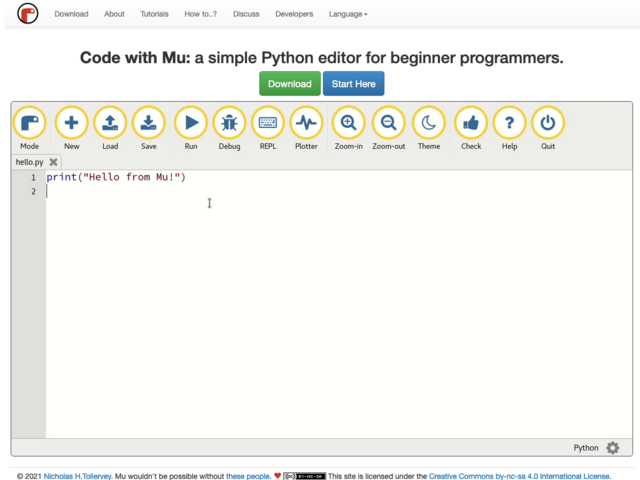 ### (3)软件代码 - 输入简单LED灯闪烁控制代码,如下。 ```python import board import digitalio import time led = digitalio.DigitalInOut(board.LED) led.direction = digitalio.Direction.OUTPUT while True: led.value = True time.sleep(0.5) led.value = False time.sleep(0.5) ``` ### (4)演示 - 视频效果: [localvideo]5e0f2d81c62df98c5720a1ff357e2c44[/localvideo] ## 基础任务一 - 控制板载炫彩LED,跑马灯点亮和颜色变换 ### 原理 - 板载幻彩灯:  - 参考WS2812的资料:[参考WS2812博文](https://i-blog.csdnimg.cn/blog_migrate/db654c3e11510abcd6dfcfffe97da35b.png "参考WS2812博文") - 对于单总线控制幻彩灯,最关键就是发送准确的时序到逐个灯珠。 - 针对此CiruitPython进行编程的好处,就是可以调用写好的库:neopixel和rainbowio,使得整个控制效率大大提高。 ### 硬件 - 板子10颗幻彩灯珠,采用单总线方式串联连接,主控通过发送控制时序,即可逐个点亮或全点亮,或控制颜色变化。 ### 软件 演示任务的源代码: ```python # SPDX-FileCopyrightText: 2017 John Edgar Park for Adafruit Industries # # SPDX-License-Identifier: MIT # Circuit Playground NeoPixel import time import board from rainbowio import colorwheel import neopixel # 配置WS2812的控制脚及亮度 pixels = neopixel.NeoPixel(board.NEOPIXEL, 10, brightness=0.2, auto_write=False) # 可配置4种三色灯点灯模式,配置1打开 # choose which demos to play # 1 means play, 0 means don't! color_chase_demo = 1 flash_demo = 1 rainbow_demo = 1 rainbow_cycle_demo = 1 # 流水灯 def color_chase(color, wait): for i in range(10): pixels = color time.sleep(wait) pixels.show() time.sleep(0.5) # 彩虹环 def rainbow_cycle(wait): for j in range(255): for i in range(10): rc_index = (i * 256 // 10) + j * 5 pixels = colorwheel(rc_index & 255) pixels.show() time.sleep(wait) # 彩虹颜色变化 def rainbow(wait): for j in range(255): for i in range(len(pixels)): idx = int(i + j) pixels = colorwheel(idx & 255) pixels.show() time.sleep(wait) RED = (255, 0, 0) YELLOW = (255, 150, 0) GREEN = (0, 255, 0) CYAN = (0, 255, 255) BLUE = (0, 0, 255) PURPLE = (180, 0, 255) WHITE = (255, 255, 255) OFF = (0, 0, 0) while True: # 流水效果 if color_chase_demo: color_chase(RED, 0.1) # Increase the number to slow down the color chase color_chase(YELLOW, 0.1) color_chase(GREEN, 0.1) color_chase(CYAN, 0.1) color_chase(BLUE, 0.1) color_chase(PURPLE, 0.1) color_chase(OFF, 0.1) # 纯色点亮 if flash_demo: pixels.fill(RED) pixels.show() # Increase or decrease to change the speed of the solid color change. time.sleep(1) pixels.fill(GREEN) pixels.show() time.sleep(1) pixels.fill(BLUE) pixels.show() time.sleep(1) pixels.fill(WHITE) pixels.show() time.sleep(1) # 彩虹色环流动效果 if rainbow_cycle_demo: rainbow_cycle(0.05) # Increase the number to slow down the rainbow. # 彩虹颜色变化 if rainbow_demo: rainbow(0.05) # Increase the number to slow down the rainbow. ``` ### 演示效果 [localvideo]c2ef1168762f7ef9af7aedac7452534b[/localvideo] ## 基础任务二 - 监测环境温度和光线,通过板载LED展示舒适程度 ### 硬件 - 开发板描述: o 1 x Temperature sensor (thermistor) o 1 x Light sensor (phototransistor). Can also act as a color sensor and pulse sensor. - 在板载带有温度传感器(电阻式)NTC thermistor (Murata NCP15XH103F03RC),可通过ADC检测其产生的电压作为输入  - 板载带有光电晶体管 亿光的 Ambient Light Sensor Surface-Mount ALS-PT19-315C/L177/TR8,该传感器模拟信号输出,可通过ADC检测其产生的电压作为检测输入  ### 软件 - 软件源码如下: - A、主要过程:初始化温度及光传感器的模拟输入ADC - B、根据采集得到的数值做LED幻彩灯的对应显示指示 ```python # SPDX-FileCopyrightText: 2017 John Edgar Park for Adafruit Industries # # SPDX-License-Identifier: MIT # Circuit Playground Light Sensor # Reads the on-board light sensor and graphs the brightness with NeoPixels import time import board import neopixel import analogio import simpleio import adafruit_thermistor # 幻彩灯显示 pixels = neopixel.NeoPixel(board.NEOPIXEL, 10, brightness=.05, auto_write=False) pixels.fill((0, 0, 0)) pixels.show() # 初始化环境光检测ADC输入检测 light = analogio.AnalogIn(board.LIGHT) # 初始化温度传感器ADC输入检测 thermistor = adafruit_thermistor.Thermistor(board.TEMPERATURE, 10000, 10000, 25, 3950) while True: # 将光亮度值 对应到幻彩灯 # light value remapped to pixel position peak = simpleio.map_range(light.value, 2000, 62000, 0, 9) print(light.value) print(int(peak)) # 输出采集到的温度值 temp_c = thermistor.temperature temp_f = thermistor.temperature * 9 / 5 + 32 print("Temperature is: %f C and %f F" % (temp_c, temp_f)) # 根据光亮度及温度值 进行点亮不同颜色和不同灯珠数量 for i in range(0, 9, 1): if i 32: pixels = (255, 00, 00) elif temp_c > 30: pixels = (00, 00, 255) else: pixels = (0, 255, 0) else: pixels = (0, 0, 0) pixels.show() time.sleep(0.01) ``` ### 演示 - 检测到光变化及温度变化的演示效果。 [localvideo]069942224e9c3f1a86a5ab0e3f398de4[/localvideo] ## 基础任务三 - 接近检测——设定安全距离并通过板载LED展示,检测到入侵时,发起声音报警 ### 硬件 - 关于靠近检测,从论坛上有看到用光传感器检测光强度进行实现的。以下将利用板载的红外发射管和接收管来进行靠近检测功能。  ### 软件 - 软件实现流程分为3个部分: - A、控制红外IR进行脉冲发射 - B、打开IR接收的ADC检测,读取检测值 - C、根据检测到的ADC值进行蜂鸣告警和幻彩LED指示 ```python import time import board import analogio import digitalio from adafruit_circuitplayground import cp # 关闭幻彩灯 cp.pixels.fill((0, 0, 0)) # 设置红外IR发射管脚 ir_led = digitalio.DigitalInOut(board.IR_TX) ir_led.direction = digitalio.Direction.OUTPUT # 设置红外检测,采用ADC检测 adc = analogio.AnalogIn(board.IR_PROXIMITY) # 距离范围转换 def scale_range(value): if value43000: value = 43000 value = value - 29000 return round(value/(43000 - 29000)*10) while True: # 发射一个短脉冲时间 ir_led.value = True time.sleep(0.05) ir_led.value = False # ADC对应值 dist = adc.value print(dist) time.sleep(0.2) # 根据距离告警和指示幻彩灯 peak = scale_range(dist) for i in range(10): if i 3: cp.play_tone(440, 1) cp.pixels.show() ``` ### 演示 开发板的演示效果如下: [localvideo]273ffcd271e41869085d34ea5b0003c4[/localvideo] ## 进阶任务 - 制作不倒翁——展示不倒翁运动过程中的不同灯光效果 ### 硬件 - 检测不倒翁的各个摇摆的方向是通过板载的G-Sensor实现。  - 关于G-Sensor LIS3DH,是一颗非常通用的传感器: - 3轴MEMS加速度计,超低功耗,±2g/±4g/±8g/±16g满量程,高速I2C/SPI数字输出,内置FIFO和高性能加速度传感器,LLGA 16 3x3x1.0封装 ### 软件 - 不倒翁的演示代码实现过程包括: - A、读取G-Sensor的数值 - B、根据G-Sensor Z轴的数据判断板子是否在水平状态 - C、根据X轴和Y轴的正负号,判断不倒翁偏向的方向,从而点亮对应区域的LED以及发出蜂鸣器响声 ```python import time import board from rainbowio import colorwheel import neopixel from adafruit_circuitplayground import cp # 灯显示效果 def rainbow(wait): for j in range(0,255,25): for i in range(10): idx = int(i + j) cp.pixels = colorwheel(idx & 255) cp.pixels.show() while True: # 读取LIS3DH的加速度传感器3轴数据 x, y, z = cp.acceleration print(('x',x, 'y',y, 'z',z)) # 如果Z轴大于9.5说明处于相对水平静置状态 if z > 9.5: rainbow(0.05) cp.stop_tone() else: time.sleep(0.2) # 熄灭各个幻彩灯 for i in range(10): cp.pixels = (0, 0, 0) # 判断4个区域的加速度正负范围,从而判断不倒翁偏向的方向 if x > 0.4 and y < -0.4: for i in range(0,3,1): cp.pixels = (255, 255, 255) cp.start_tone(262) elif x > 0.4 and y > 0.4: for i in range(2,5,1): cp.pixels = (255, 255, 255) cp.start_tone(262) elif x < -0.4 and y > 0.4: for i in range(5,8,1): cp.pixels = (255, 255, 255) cp.start_tone(262) elif x < -0.4 and y < -0.4: for i in range(7,10,1): cp.pixels = (255, 255, 255) cp.start_tone(262) cp.pixels.show() ``` ### 演示 [localvideo]242145cc9043325d25a618e68178cd60[/localvideo] ## 创意任务 ### 创意任务三 水果钢琴——通过触摸水果弹奏音乐,并配合灯光效果 #### 原理 - 通过圆形板子的周边铜Pad,人手触摸产生电容变化即可感应到输入,然后播放对应的wav音频文件。 #### 硬件 -用到板载的连接pad,可以用手直接触摸,或者外引出到一个金属铜箔(硬币)上。  #### 软件 - 软件源码可参考:[808_drum_machine的演示](https://learn.adafruit.com/adafruit-circuit-playground-express/playground-drum-machine "808_drum_machine的演示") ```python # SPDX-FileCopyrightText: 2019 Kattni Rembor for Adafruit Industries # # SPDX-License-Identifier: MIT # Circuit Playground 808 Drum machine import time import board import touchio import digitalio try: from audiocore import WaveFile except ImportError: from audioio import WaveFile try: from audioio import AudioOut except ImportError: try: from audiopwmio import PWMAudioOut as AudioOut except ImportError: pass # not always supported by every board! bpm = 120 # Beats per minute, change this to suit your tempo # Enable the speaker speaker_enable = digitalio.DigitalInOut(board.SPEAKER_ENABLE) speaker_enable.direction = digitalio.Direction.OUTPUT speaker_enable.value = True # Make the input capacitive touchpads capPins = (board.A1, board.A2, board.A3, board.A4, board.A5, board.A6, board.TX) touchPad = [] for i in range(7): touchPad.append(touchio.TouchIn(capPins)) # The seven files assigned to the touchpads audiofiles = ["bd_tek.wav", "elec_hi_snare.wav", "elec_cymbal.wav", "elec_blip2.wav", "bd_zome.wav", "bass_hit_c.wav", "drum_cowbell.wav"] audio = AudioOut(board.SPEAKER) def play_file(filename): print("playing file " + filename) file = open(filename, "rb") wave = WaveFile(file) audio.play(wave) time.sleep(bpm / 960) # Sixteenth note delay while True: for i in range(7): if touchPad.value: play_file(audiofiles) ``` #### 演示 [localvideo]81c2029e0261f5365ac960418f560cfc[/localvideo] ### 自定义:摇摇乐 #### 原理 - 利用板载的G-Sensor检测板子的倾角 - 计算得到对应倾角,对应当前重力倾角对应的LED灯珠 - 根据灯珠位置,播放不同的声音 #### 源码 ```python # SPDX-FileCopyrightText: 2021 ladyada for Adafruit Industries # SPDX-License-Identifier: MIT """Gravity Pulls Pixel This program uses the Circuit Playground's accelerometer to position a white pixel as if gravity were pulling it. Flip the switch left (toward the notes) to turn on debugging messages and slow down the action. See a code walkthrough here: https://youtu.be/sZ4tNOUKRpw """ import time import math from adafruit_circuitplayground import cp PIXEL_SPACING_ANGLE = 30 STANDARD_GRAVITY = 9.81 BACKGROUND_COLOR = 0, 0, 64 MIN_BRIGHTNESS = 15 # Minimum brightness for anti-aliasing LIGHTING_ARC_LENGTH = 45 def compute_pixel_angles(): """Return a list of rotation angles of the ten NeoPixels. On the Circuit Playground there are ten pixels arranged like the 12 hours of a clock, except that positions 6 and 12 are empty. The numbers in the list are the angles from the (x, y) accelerometer values for each pixel when the Circuit Playground is rotated with that pixel at the bottom. For example, with pixel 0 at the bottom (and pixel 5 at the top), the accelerometer’s (x, y) values give an angle of 300°. Rotated clockwise 1/12 turn (30°), so that pixel 1 is at the bottom, the angle is 330°. """ return [ (300 + PIXEL_SPACING_ANGLE * n) % 360 for n in range(12) if n not in (5, 11) ] def degrees_between(a1, a2): smaller = min(a1, a2) larger = max(a1, a2) return min(larger - smaller, 360 + smaller - larger) def pixel_brightness(distance_from_down, accel_magnitude): """Return the a brightness for a pixel, or None if the pixel is not in the lighting arc""" half_lighting_arc_length = LIGHTING_ARC_LENGTH / 2 if accel_magnitude < 0.1 or distance_from_down > half_lighting_arc_length: return None normalized_nearness = 1 - distance_from_down / half_lighting_arc_length scale_factor = (255 - MIN_BRIGHTNESS) * accel_magnitude color_part = MIN_BRIGHTNESS + round(normalized_nearness * scale_factor) return color_part def angle_in_degrees(x, y): """Return the angle of the point (x, y), in degrees from -180 to 180""" return math.atan2(y, x) / math.pi * 180 def positive_degrees(angle): """Convert -180 through 180 to 0 through 360""" return (angle + 360) % 360 cp.pixels.brightness = 0.1 # Adjust overall brightness as desired, between 0 and 1 pixel_positions = compute_pixel_angles() # The seven files assigned to the touchpads audiofiles = ["bd_tek.wav", "elec_hi_snare.wav", "elec_cymbal.wav", "elec_blip2.wav", "bd_zome.wav", "bass_hit_c.wav", "bd_tek.wav", "bd_zome.wav", "elec_cymbal.wav", "drum_cowbell.wav"] while True: debug = cp.switch # True is toward the left accel_x, accel_y = cp.acceleration[:2] # Ignore z down_angle = positive_degrees(angle_in_degrees(accel_x, accel_y)) magnitude_limit = STANDARD_GRAVITY normalized_magnitude = ( min(math.sqrt(accel_x * accel_x + accel_y * accel_y), magnitude_limit) / magnitude_limit ) pixels_lit = [] for i, pixel_position in enumerate(pixel_positions): pe = pixel_brightness( degrees_between(pixel_position, down_angle), normalized_magnitude ) cp.pixels = (pe, pe, pe) if pe else BACKGROUND_COLOR if pe: pixels_lit.append((i, pe)) cp.play_file(audiofiles) if debug: lit_formatted = ", ".join(("{}: {:>3d}".format(p, i) for p, i in pixels_lit)) print( "x: {:>6.2f}, y: {:>6.2f}, angle: {:>6.2f}, mag: {:>3.2f}, pixels: [{}]".format( accel_x, accel_y, down_angle, normalized_magnitude, lit_formatted ) ) #time.sleep(0.5) ``` #### 演示 - 演示部分见本帖开头! ## 整合源码 - 以上任务所有源代码: ## 总结 - 2024 FM1已经是我参加的第5次的FM活动,非常感觉Digikey和EEWorld,让我有机会可以动手体验这些有趣好玩的板子!同时,也看到论坛其他出色的开发者的设计。 - 最后,感触最大的就是大家的动手能力太强了!大家都很踊跃在参加,在分享!2024的FM2我没有提交申请,当然也就没有机会玩到对应的板子。接着,需要投入时间到创意DIY上了~~~
-
回复了主题帖: 【2024 DigiKey创意大赛】RPI5翻译机---2 RPI5物料开箱-2
可以在52840上跑zephyr上的broadcast audio source(controller端),在RP5上跑BlueZ。 Bluetooth: Broadcast Audio Source — Zephyr Project Documentation
- 【Follow me第二季第4期】RP2350-Pico2试玩体验
- 【Follow me第二季第4期】PB03蓝牙模块+小程序体验
- 【Follow me第二季第4期】任务汇总
- 【Follow me第二季第1期】微型低压步进电机驱动芯片试用
- 【Follow Me第二季第4期】开箱帖
- 冲【Follow Me第二季第4期】已下单,等板子!!!!
- 2024DigiKey创意大赛】【自行车智能灯】汇总提交
- 【Follow me第二季第1期】任务汇总+简单创意:摇摇乐
- 【2024DigiKey创意大赛】【自行车智能灯】开箱贴ESP32-S3-LCD-EV-BOARD&ICM2094
- 【Follow me第二季第1期】开箱帖:板子收到啦啦啦!!!
最近访客
统计信息
已有76人来访过
- 芯积分:436
- 好友:--
- 主题:61
- 回复:54
留言

现在还没有留言
推荐博文
- 国产!瑞芯微RK3576(八核@2.2GHz+6T NPU)工业开发板规格书
- 开环、闭环
- OpenHamrony4.0去除锁屏是一种什么体验?触觉智能给你支支招
- DIY一个袖珍实验电源
- 汽车PKE无钥匙进入系统如何实现?拆解Si3933资料告诉你
- 《STM32H7S78-DK 开发套件二周目评测:简单声音采集之频率检测与显示》
- 《STM32H7S78-DK 开发套件二周目评测:简单声音采集之驱动MAX4466高精度声音传感器》
- 伺服电机滑环的主要组成部分,伺服电机滑环怎么安装?
- GB 4824-2019 CISPR 11-2016
- 电驱动钛丝(SMA)的可靠性设计(6) 温度控制
- 有源晶振和无源晶振的区别
- 【2024 DigiKey创意大赛】车载后方来车预警系统
- 【Follow me第二季第3期】进阶任务:示例程序中新增命令打印信息
- GB/T 17626.6-2008 电磁兼容 试验和测量技术 射频场感应的传导骚扰抗扰度
- EMC测试基本环境要求