ShallGoing
- 2024-12-28
-
发表了主题帖: 【Follow me第二季第4期】任务汇总
# 前言 最近参加了一个followme的活动,活动的任务是ardunio rp2024 connect的板子,主要完成三个任务: 1. 搭建环境并开启第一步Blink三色LED / 串口打印Hello DigiKey & EEWorld!; 2. 学习IMU基础知识,调试IMU传感器,通过串口打印六轴原始数据; 3. 学习PDM麦克风技术知识,调试PDM麦克风,通过串口打印收音数据和音频波形。 **视频[链接]**(https://training.eeworld.com.cn/video/42208) 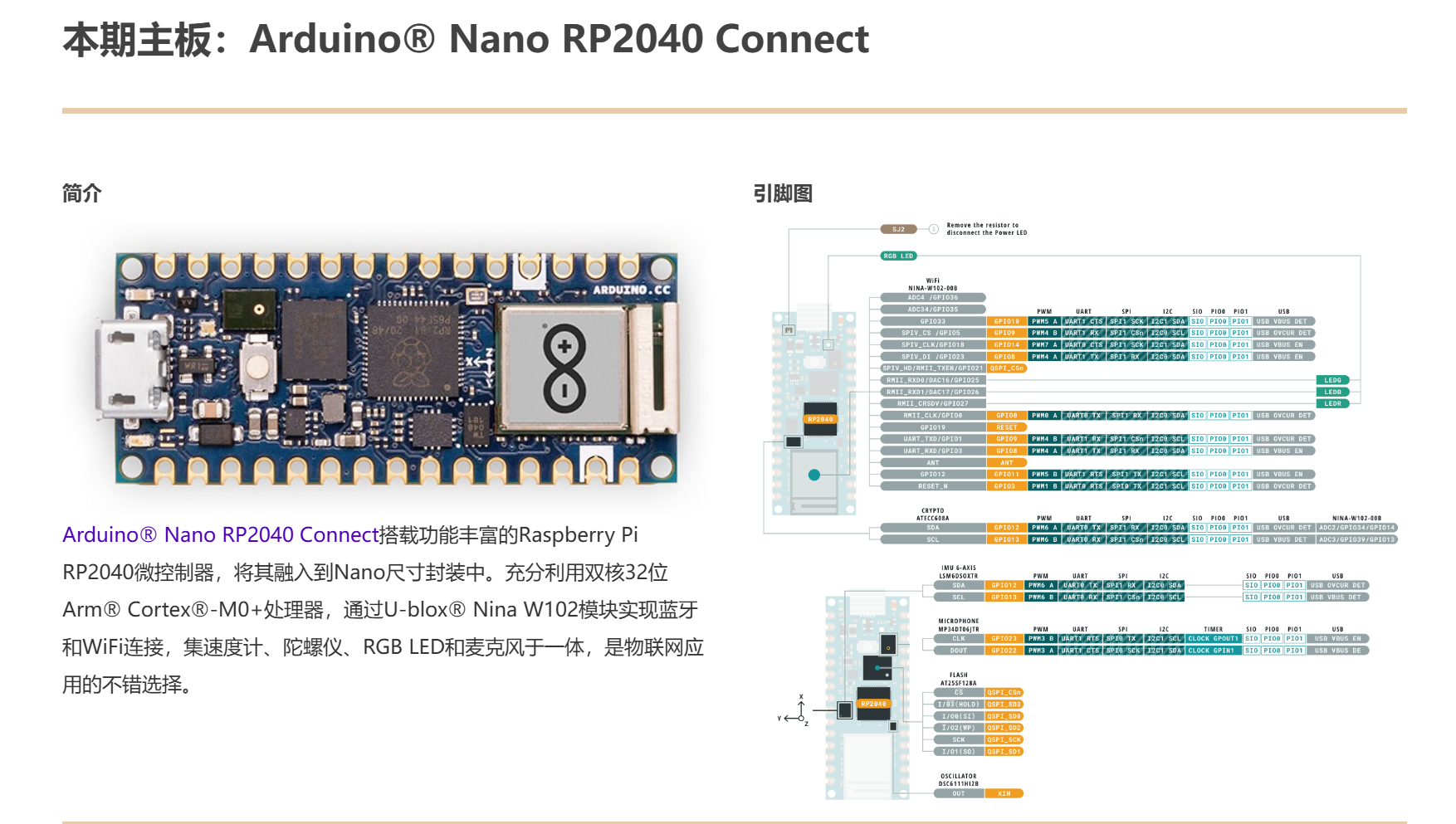 纯新手,朋友介绍过来玩的硬件。啥也不会,一边学一边玩吧。 干啥第一件事肯定就是搭环境。 先去ardunio的[官网](https://www.arduino.cc/en/software),找安装包,安装ardunio的ide。 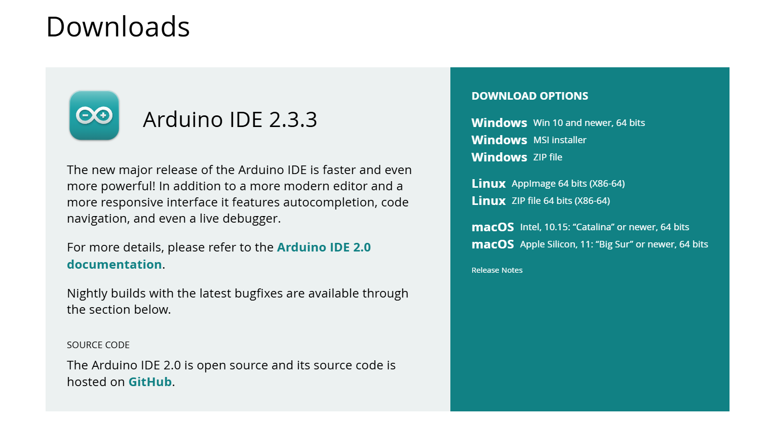 现在板子到日本了,估计过两天就到了。 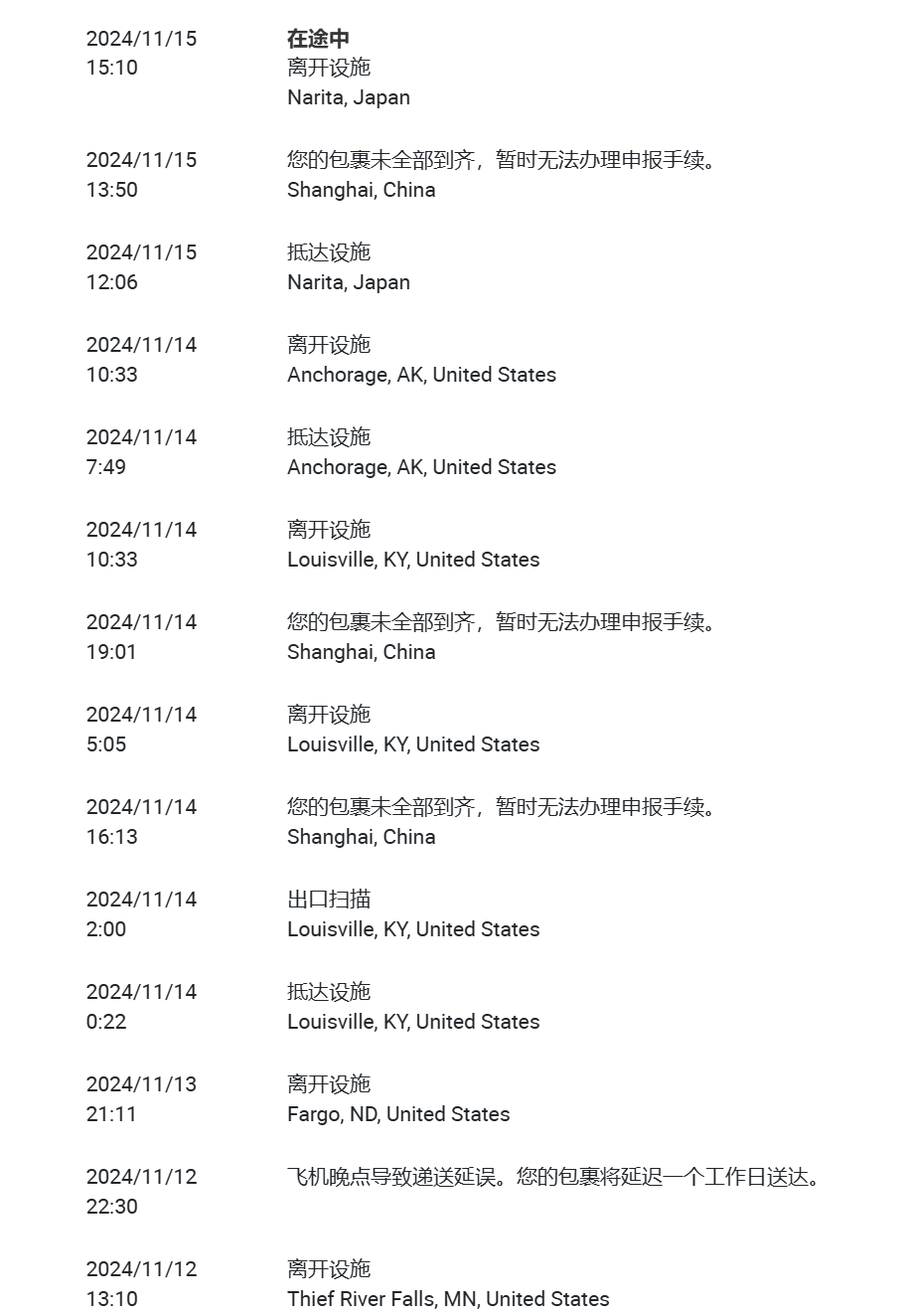 --- 今天终于到了。开箱!!! 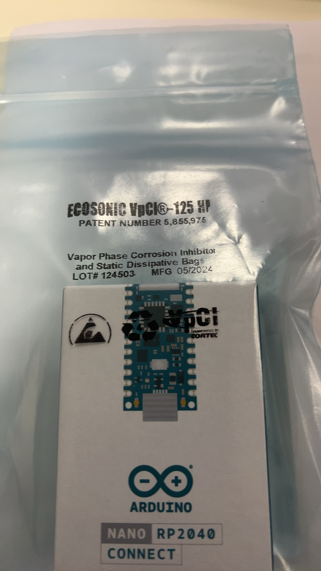 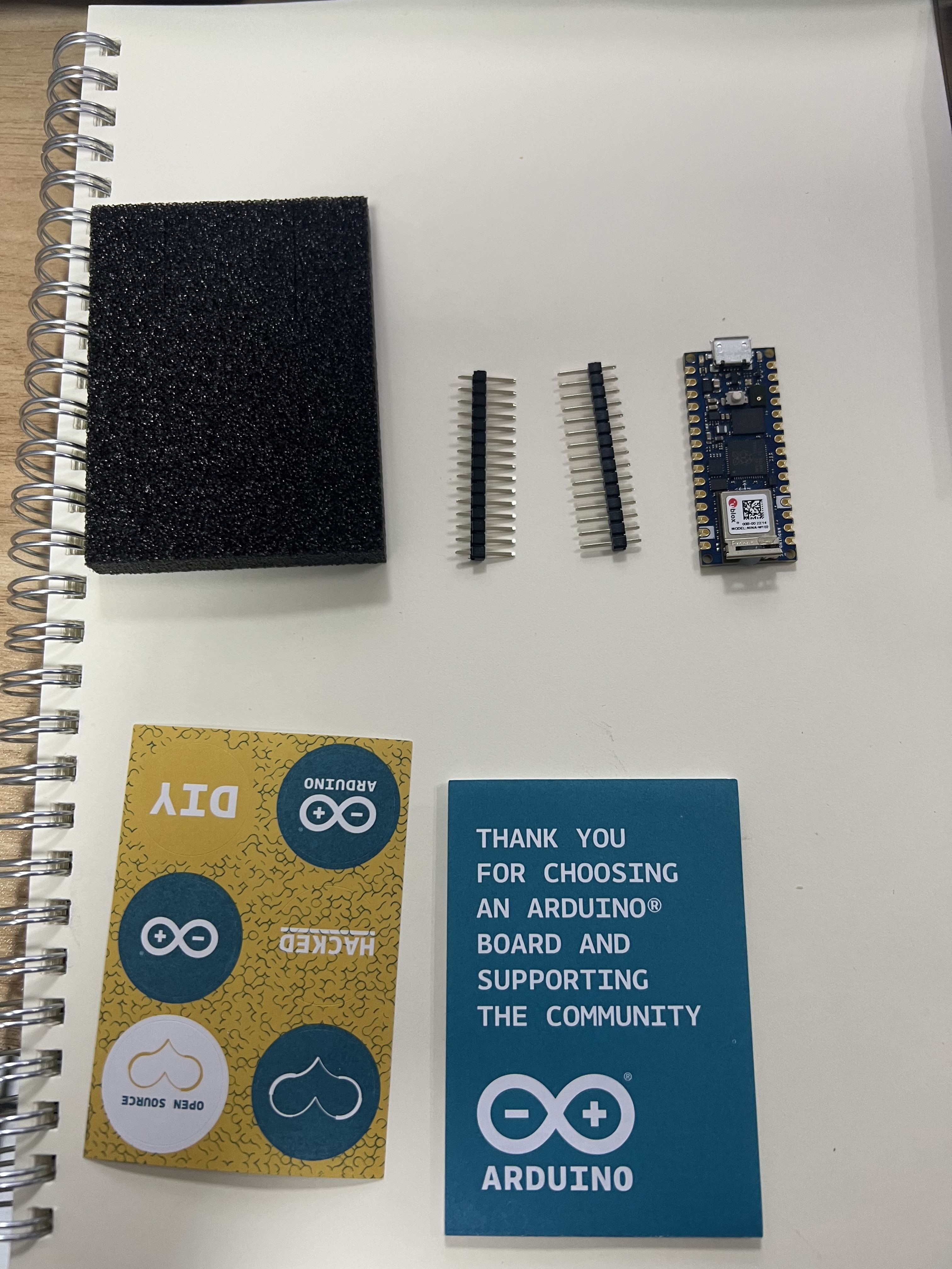 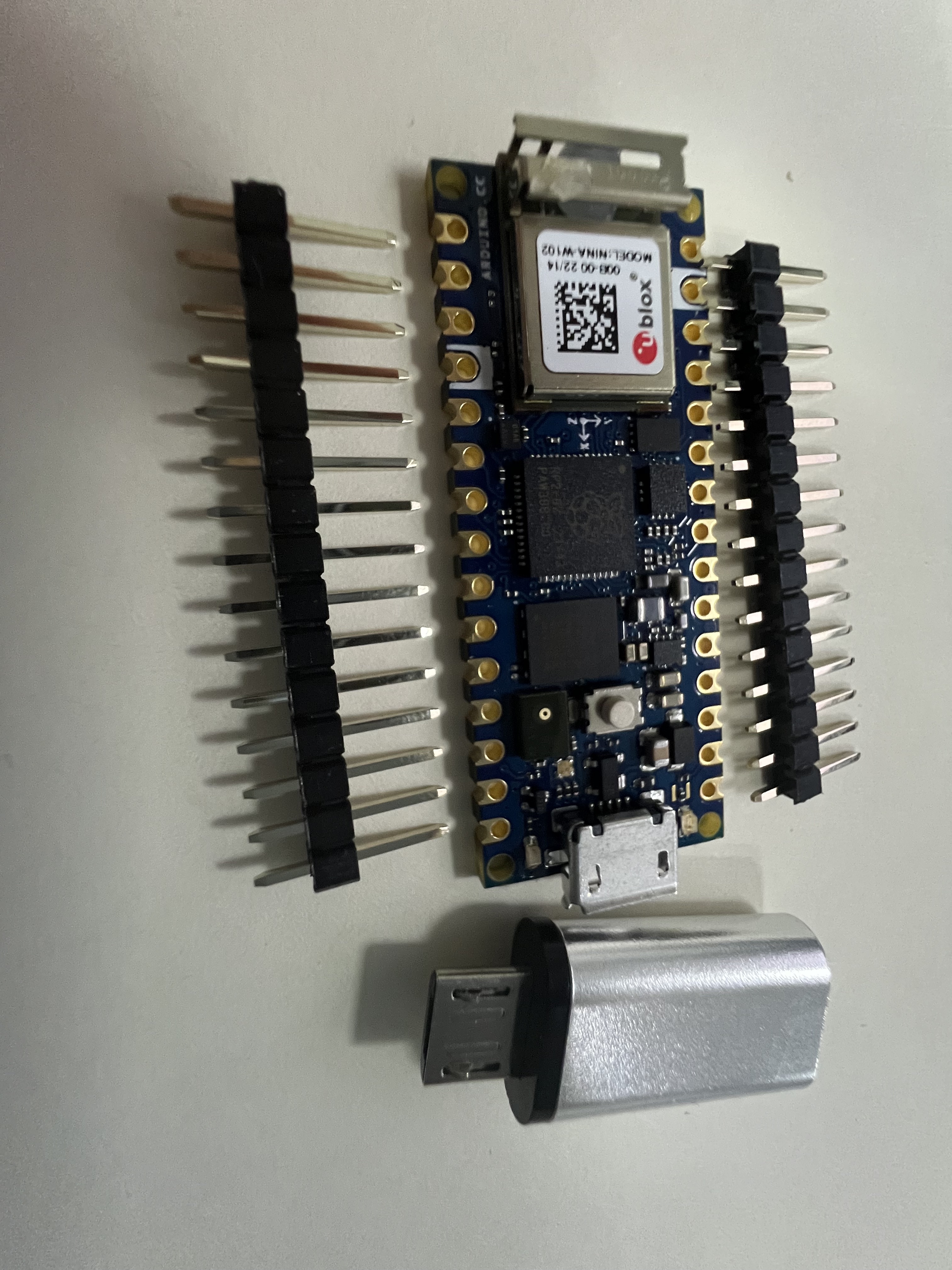 由于手头没有mirco的线,先用这个转换头看看。 --- # 尝试 ## 1.配置开发环境 - [x] 安装ardunio2.3.3 IDE - [x] 安装板包 搜索开发板的名字 **arduino nano rp2040 connect** 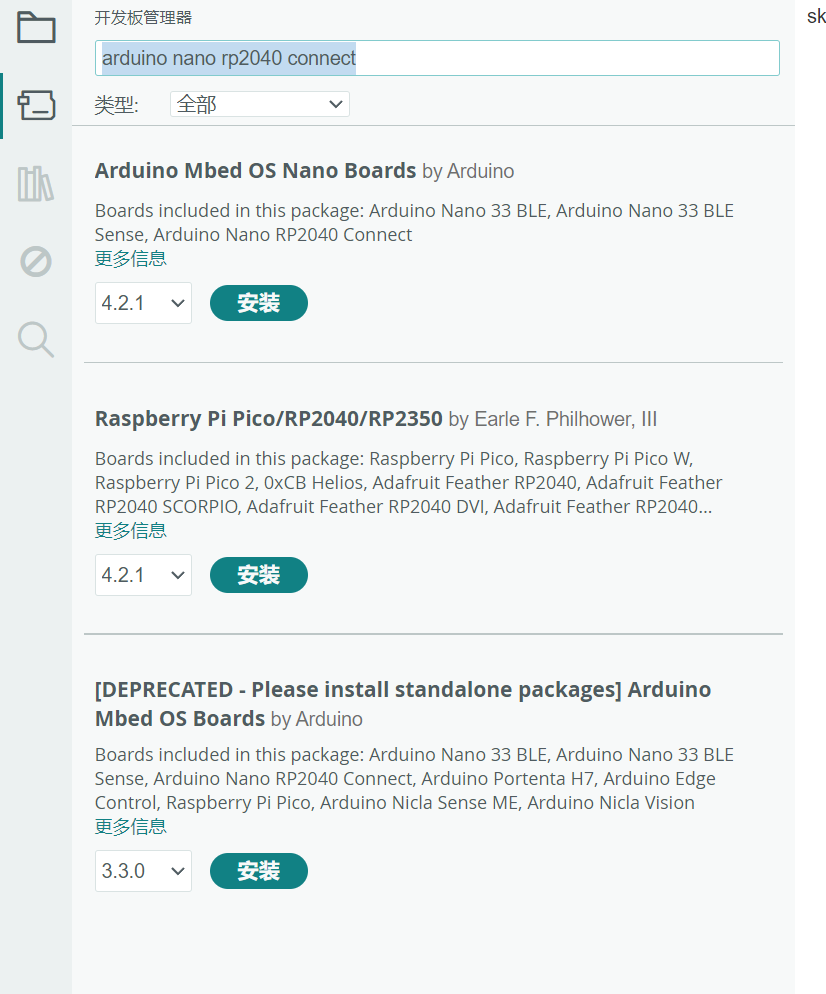 ## 2.点灯 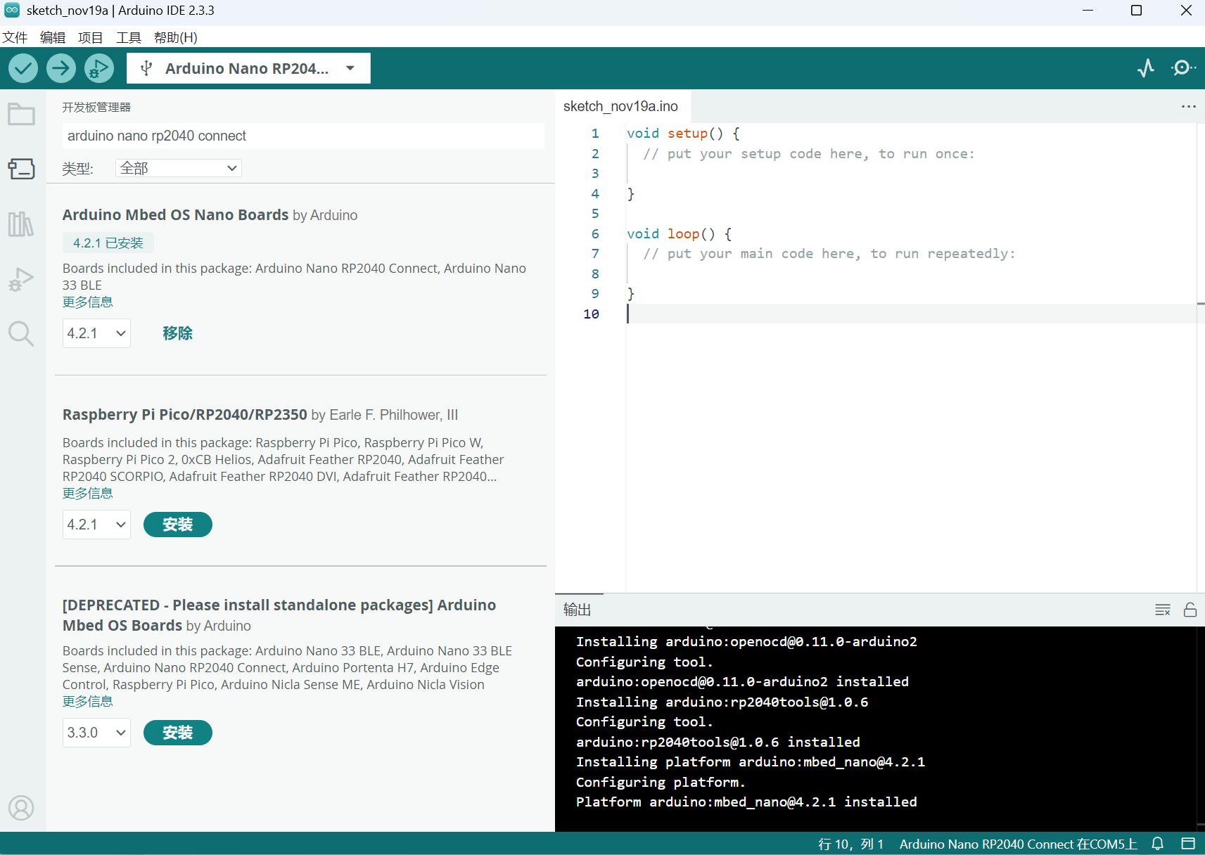 在上述的情况下已经完成安装的操作,我们的板子在连接的时候就一直闪烁。表现为一个红灯间接闪烁,一个灯变色间接闪烁,一个绿灯常亮。 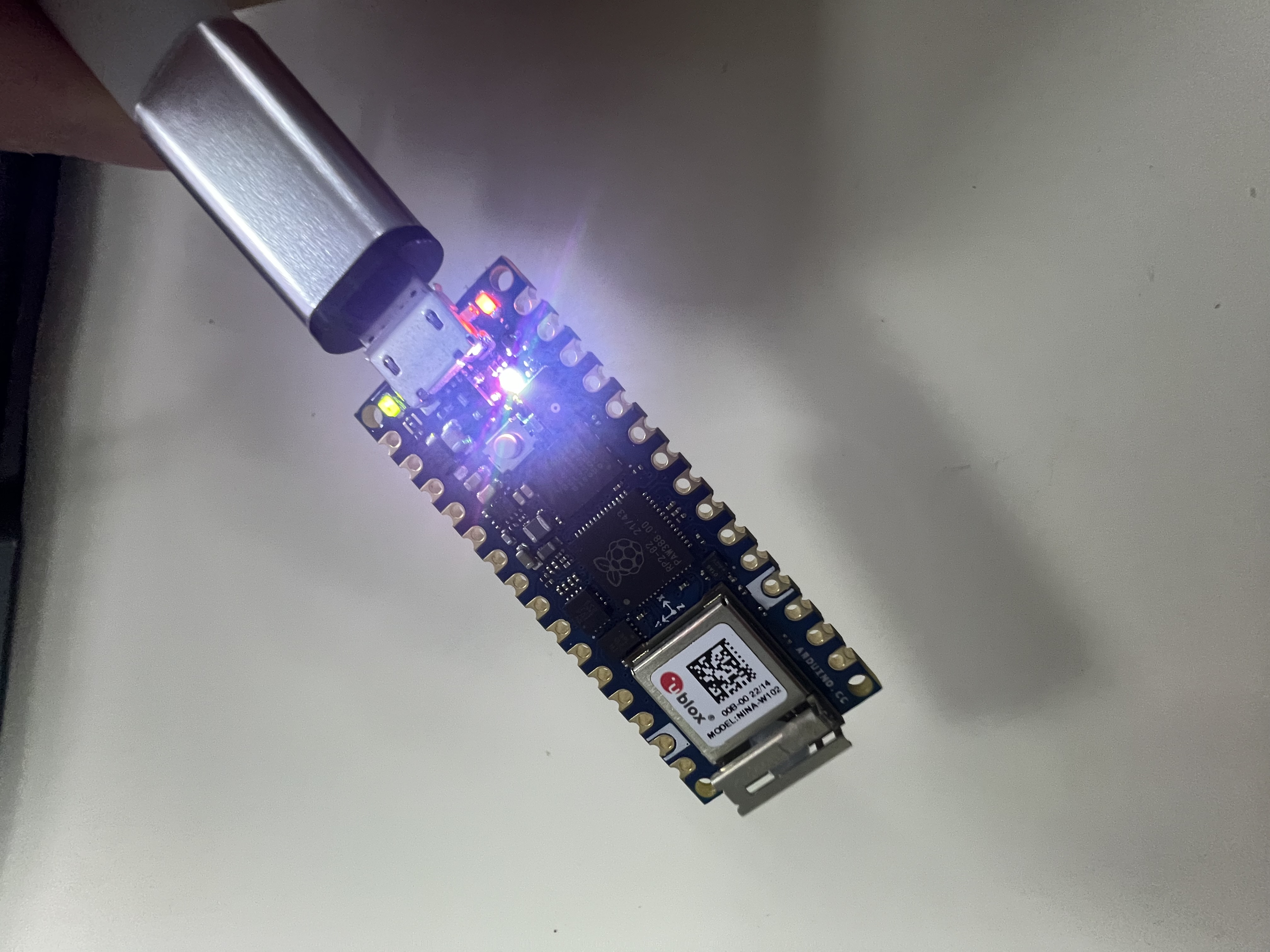 ---- 下面开始点灯的操作 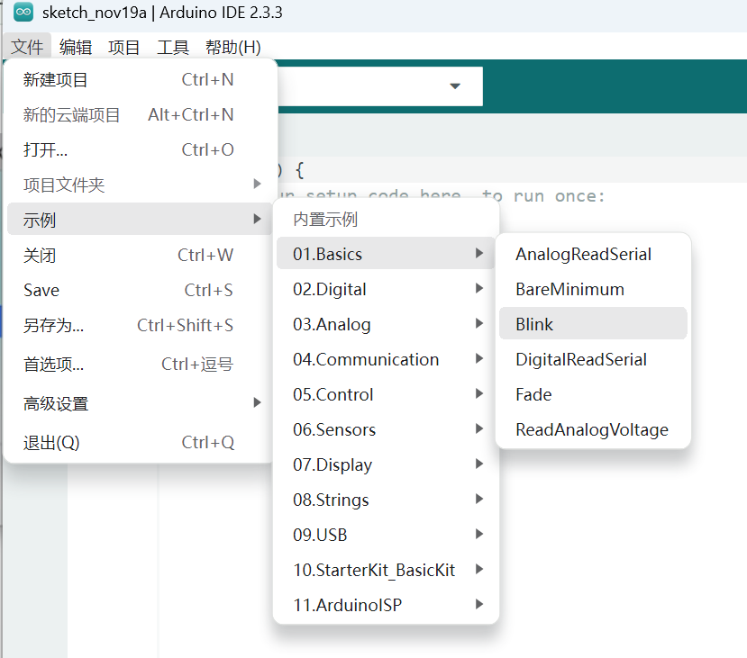 选择Blink,然后点击上传按钮 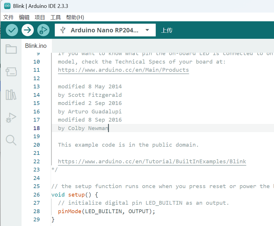 我们可以看到,板子的灯也变了 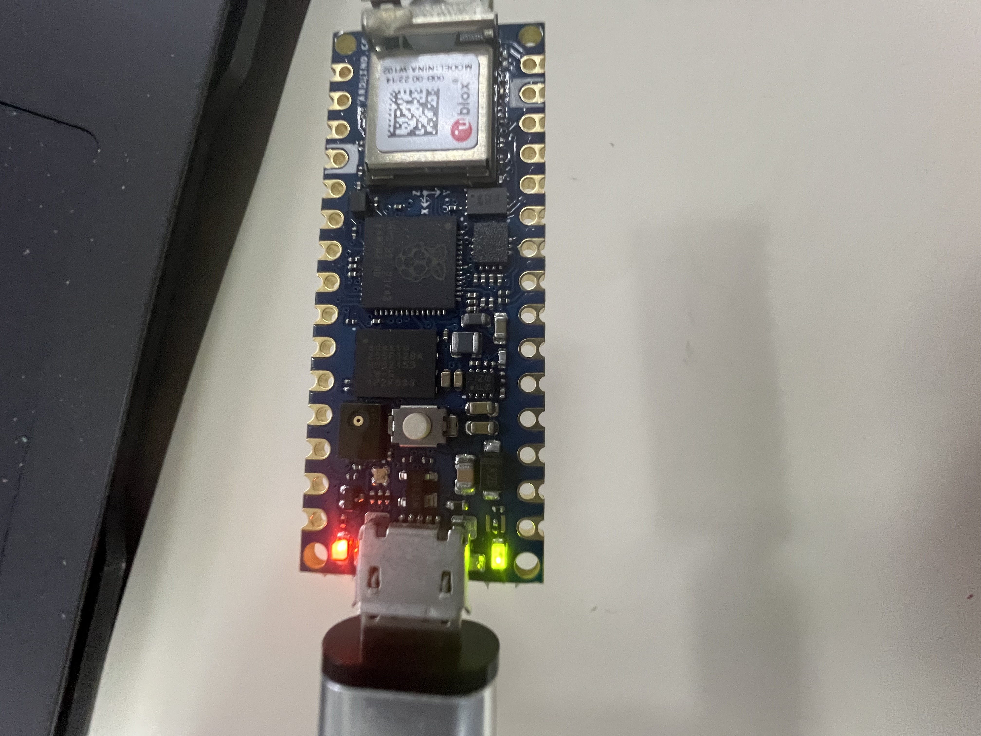 ## 恭喜你完成了点灯的操作!!!😘 # 任务一:搭建环境并开启第一步Blink三色LED / 串口打印Hello DigiKey & EEWorld!; ## 1.查看官方的引脚图 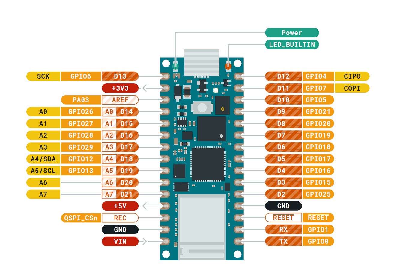 可以看到我们刚才点灯调用的是LED_BUILTIN的引脚。找到我们本次任务的采用的RGBLED的引脚。 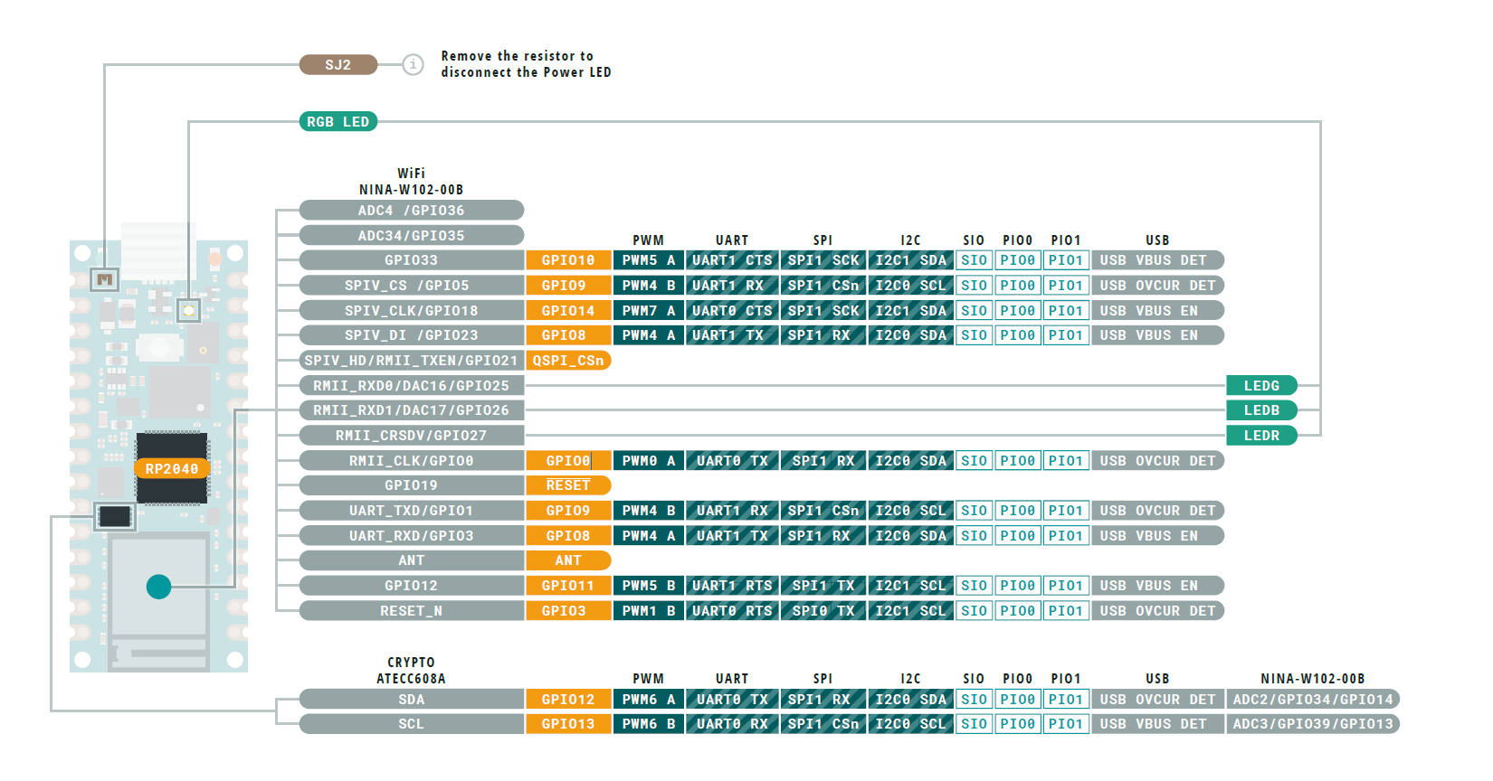 --- 因为之前没搞过硬件不太懂,想当然的认为这里的引脚是RGB LED 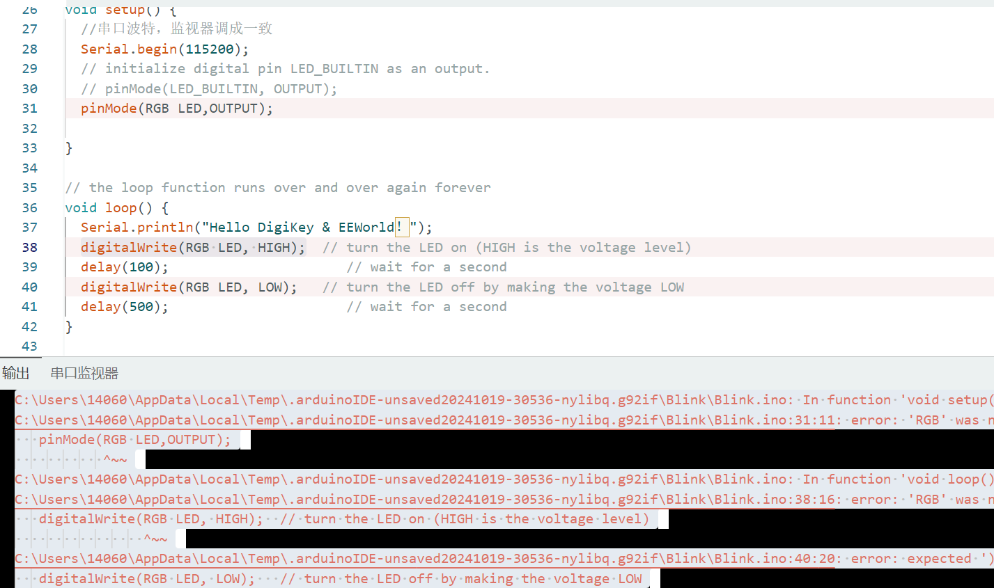 一片红灯,我得试试是不是刚才引脚图里面的LEDR/LEDG/LEDB。 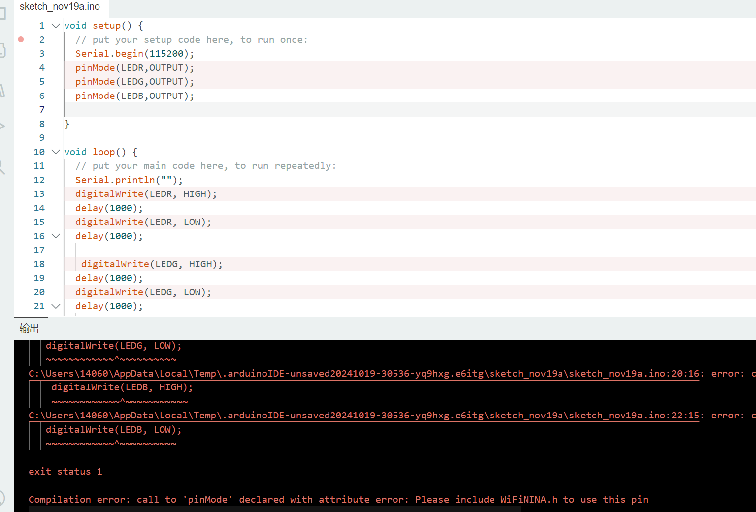 得偿所愿,也是一排红灯。但是有提示,提示这个pin脚在WIFININA的库里面才能使用。我又去[官网](https://docs.arduino.cc/hardware/nano-rp2040-connect/#features)找到开发文档,相见恨晚!! --- 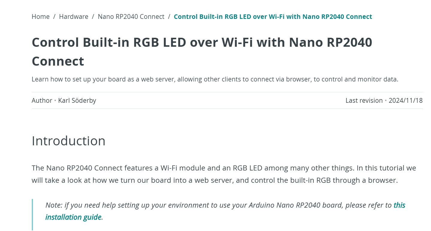 内置的LED。得调库才行。早点发现开发文档就好了。 ## 2.安装WIFININA库 好了开始装库WIFININA。 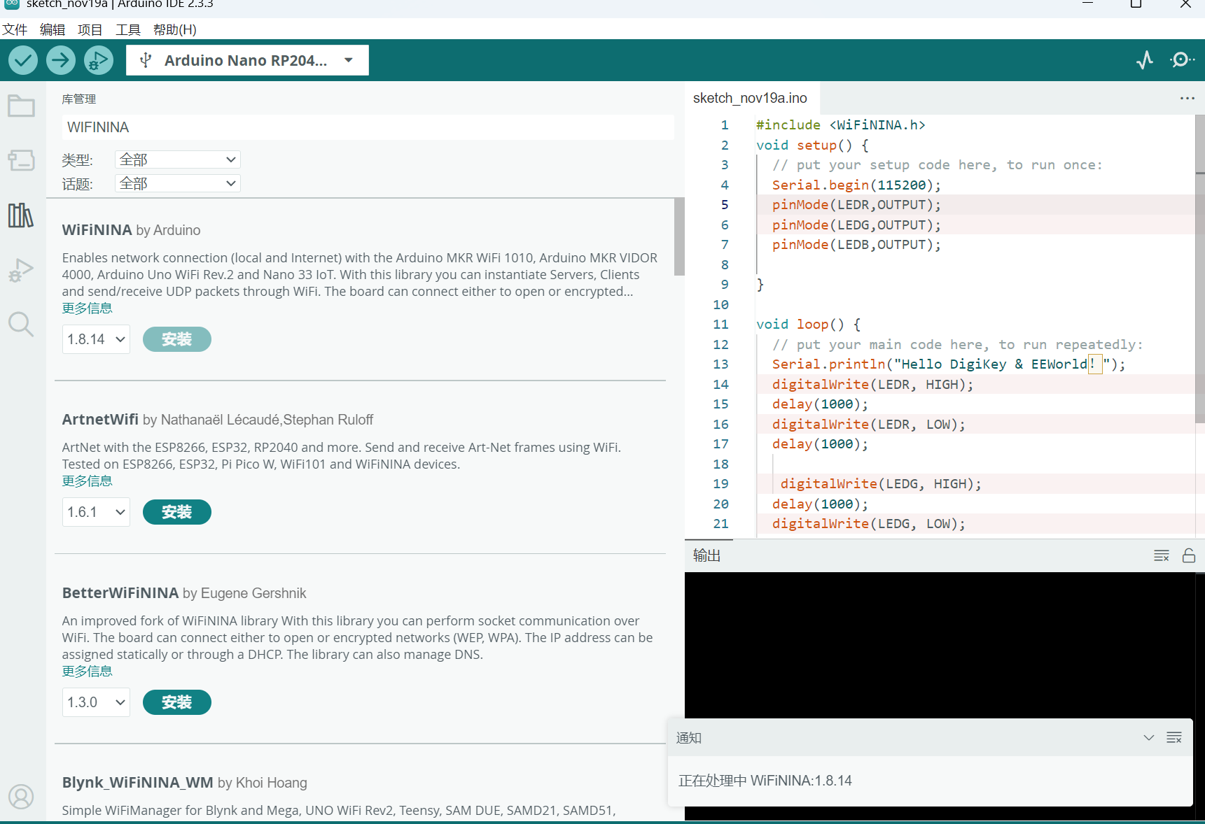 ## 3.成功点亮 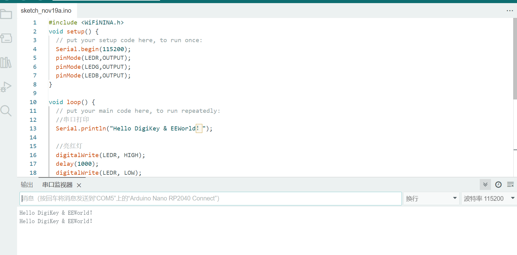 运行成功。代码如下: ```cpp #include void setup() { // put your setup code here, to run once: Serial.begin(115200); pinMode(LEDR,OUTPUT); pinMode(LEDG,OUTPUT); pinMode(LEDB,OUTPUT); } void loop() { // put your main code here, to run repeatedly: //串口打印 Serial.println("Hello DigiKey & EEWorld!"); //亮红灯 digitalWrite(LEDR, HIGH); delay(1000); digitalWrite(LEDR, LOW); delay(1000); //亮绿灯 digitalWrite(LEDG, HIGH); delay(1000); digitalWrite(LEDG, LOW); delay(1000); //亮蓝灯 digitalWrite(LEDB, HIGH); delay(1000); digitalWrite(LEDB, LOW); delay(1000); } ``` 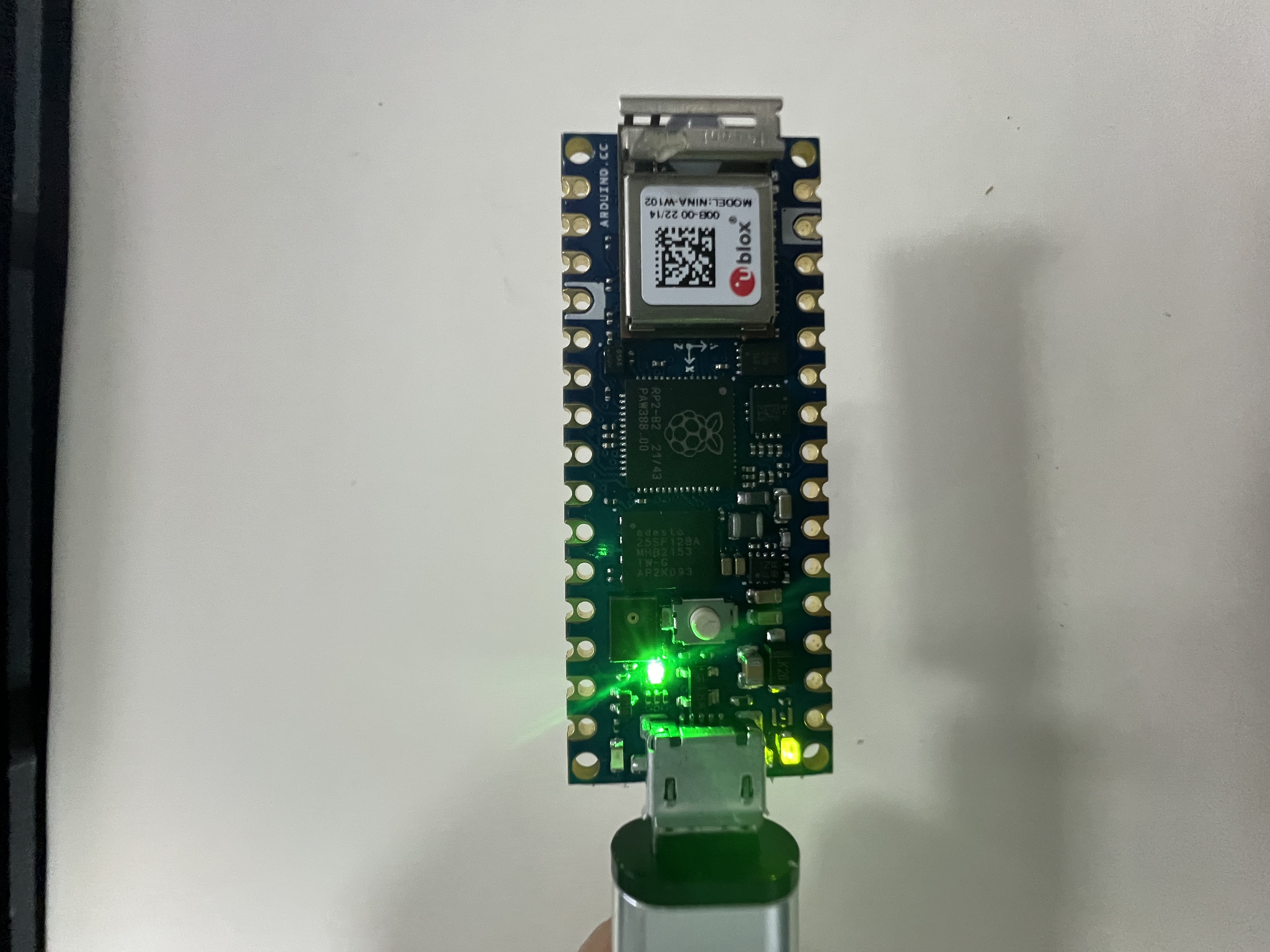 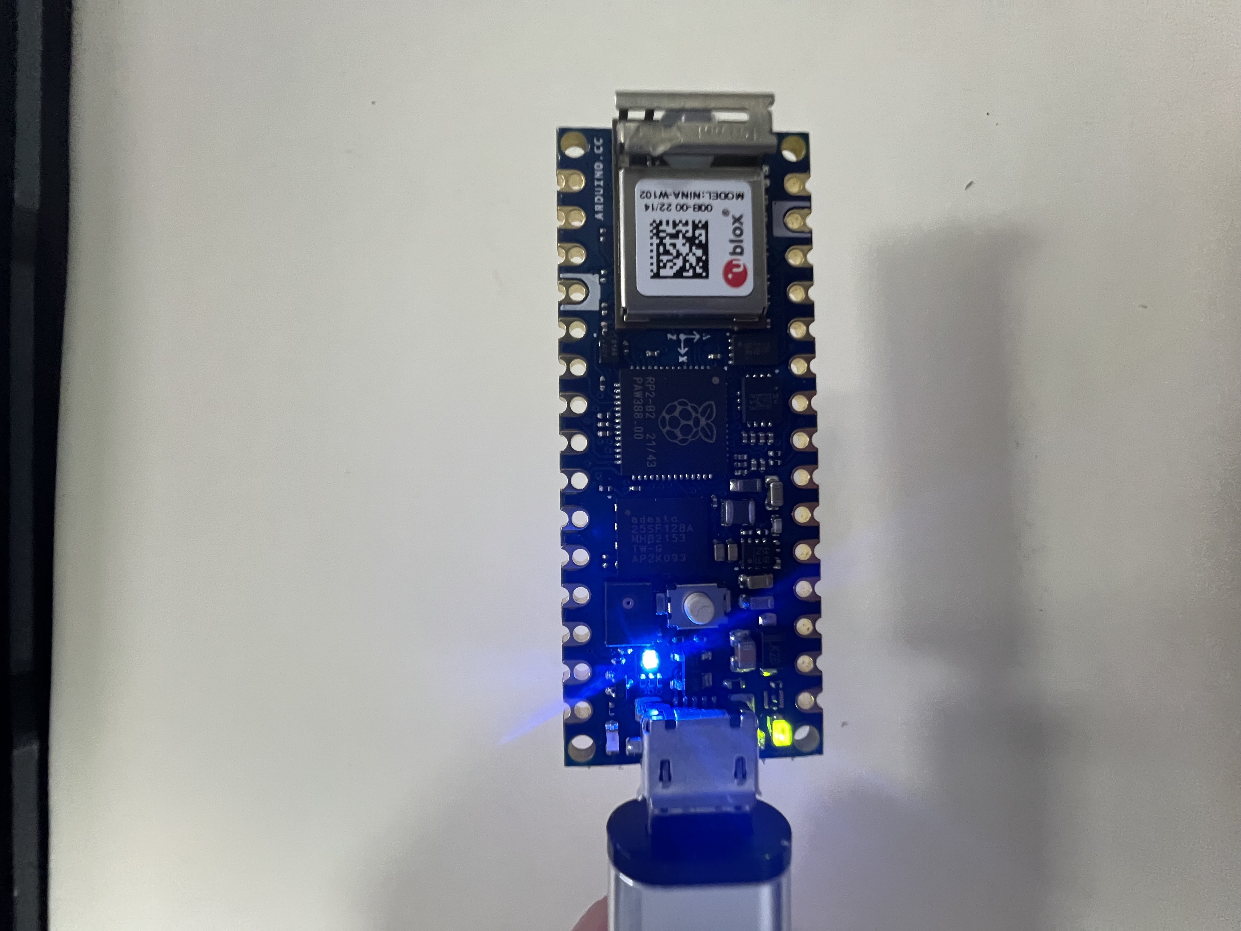 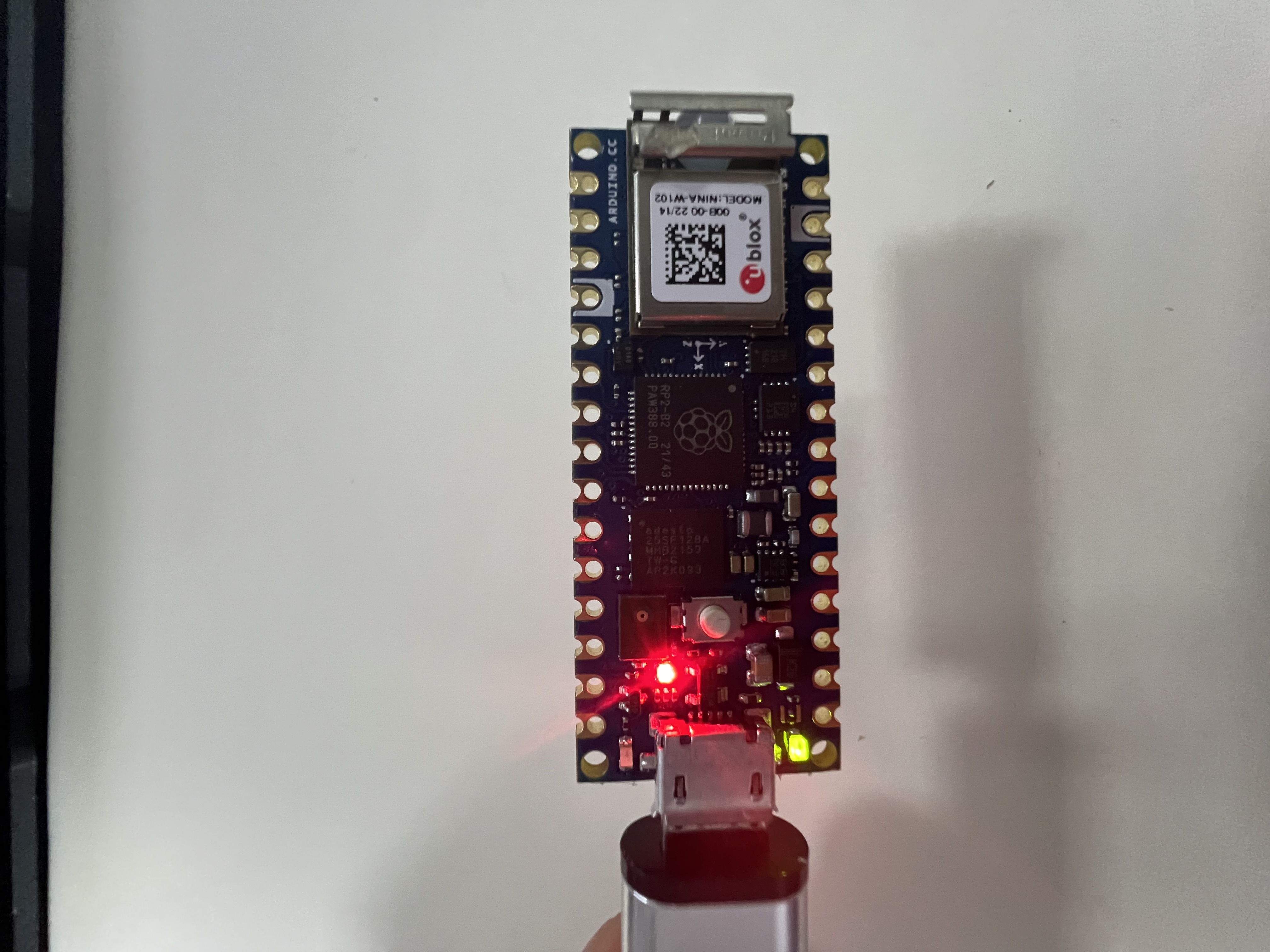 ## 任务一完成 # 任务二:学习IMU基础知识,调试IMU传感器,通过串口打印六轴原始数据 要学习 IMU (惯性测量单元) 的基础知识,并通过 Arduino IDE 调试 IMU 传感器以通过串口打印六轴原始数据,可以按照以下步骤操作: --- ## **1. 什么是 IMU?** IMU 是一种集成传感器模块,通常包含以下传感器: - **加速度计 (Accelerometer)**:用于测量线性加速度 (单位:g)。 - **陀螺仪 (Gyroscope)**:用于测量角速度 (单位:°/s 或 rad/s)。 有些 IMU 还包含磁力计 (Compass) 和温度计,但基础的六轴 IMU 只包含加速度计和陀螺仪。 查阅官方文档可知,Arduino Nano RP2040 Connect 板载 IMU 是 **LSM6DSOX**,它是一个六轴传感器: - **加速度计 (Accelerometer)**:测量线性加速度 (单位:m/s2)。 - **陀螺仪 (Gyroscope)**:测量角速度 (单位:°/s)。 ## 2.安装Arduino_LSM6DSOX库 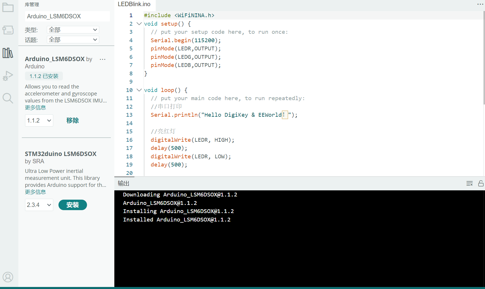 新建一个开始新的任务。 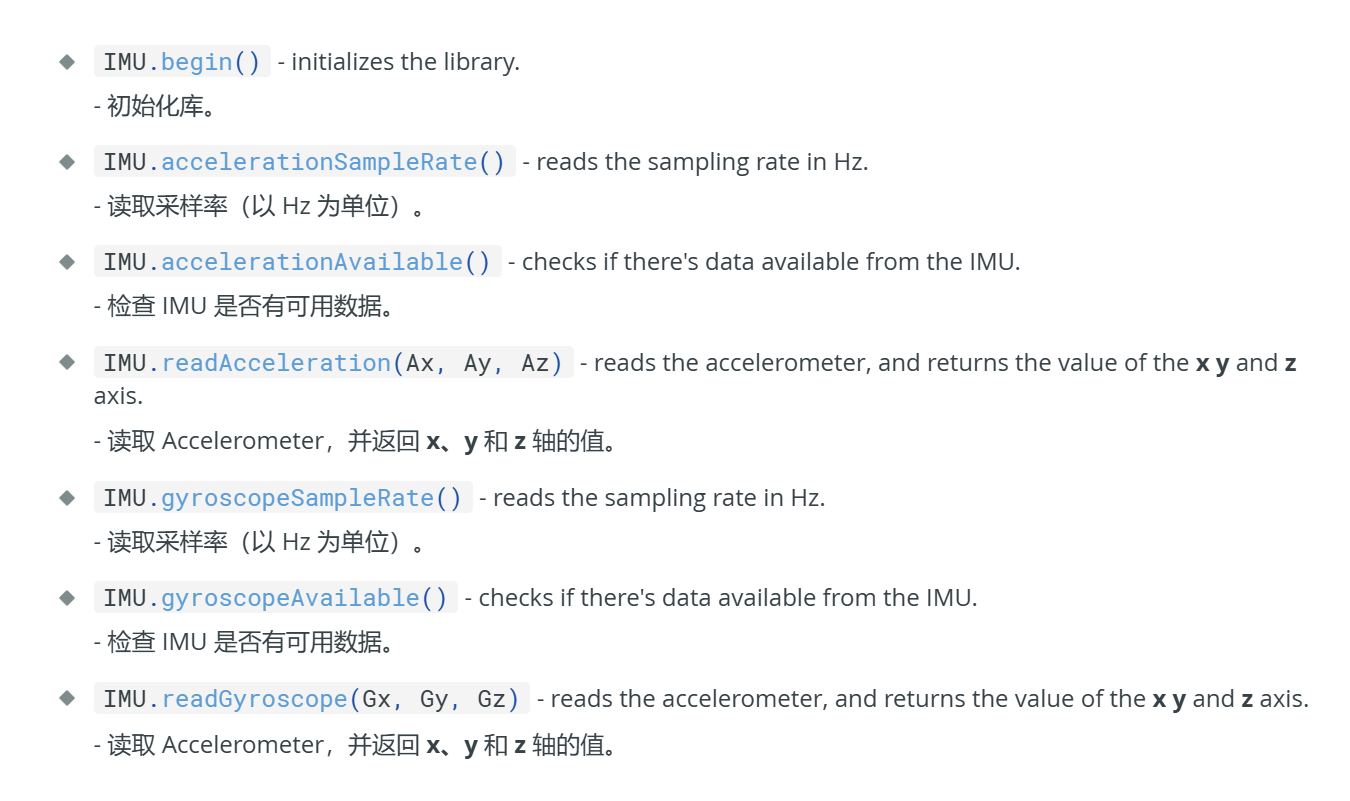 根据官方文档的函数,我们可以得到如下代码: ```cpp #include // 引入 LSM6DSOX 库 void setup() { // put your setup code here, to run once: Serial.begin(115200); // 初始化 IMU if (!IMU.begin()) { Serial.println("无法检测到 LSM6DSOX 传感器!"); while (1); // 停止运行 } Serial.println("LSM6DSOX 初始化成功!"); } void loop() { // put your main code here, to run repeatedly: // 检测加速度和陀螺仪是否可用 if (IMU.accelerationAvailable() && IMU.gyroscopeAvailable()) { // 读取加速度数据 (单位:m/s2) IMU.readAcceleration(Ax, Ay, Az); // 读取陀螺仪数据 (单位:°/s) IMU.readGyroscope(Gx, Gy, Gz); // 打印加速度数据 Serial.print("加速度 (m/s2): "); Serial.print("X = "); Serial.print(Ax); Serial.print(", Y = "); Serial.print(Ay); Serial.print(", Z = "); Serial.println(Az); // 打印陀螺仪数据 Serial.print("陀螺仪 (°/s): "); Serial.print("X = "); Serial.print(Gx); Serial.print(", Y = "); Serial.print(Gy); Serial.print(", Z = "); Serial.println(Gz); Serial.println(); // 空一行 } delay(100); // 延时,控制数据刷新频率 } ``` ## 3.查看结果 运行查看串口结果: 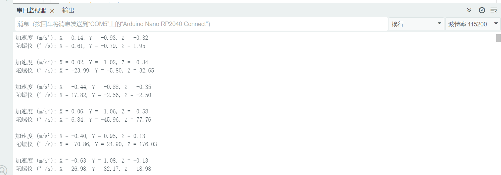 # 任务三:学习PDM麦克风技术知识,调试PDM麦克风,通过串口打印收音数据和音频波形。 ## 1.准备工作 **PDM 麦克风** 使用脉冲密度调制技术输出数字音频数据,其输出信号需要经过解码转换为 PCM(脉冲编码调制)数据,才能被处理为音频信号。 **板载麦克风型号**:Nano RP2040 Connect 上的 PDM 麦克风型号为 **MP34DT06JTR**。 PDM的库在安装IDE的集成在里面了 ## 2.撰写代码 ```cpp #include // 定义缓冲区大小(可以调整以适应需求) #define BUFFER_SIZE 512 // 缓冲区存储麦克风数据 short buffer[BUFFER_SIZE]; // 记录是否有新数据的标志 volatile int bytesRead;; // 初始化采样率和通道数 const int sampleRate = 16000; // 16 kHz 采样率 const int numChannels = 1; // 单声道 void setup() { // 初始化串口 Serial.begin(115200); while (!Serial) { delay(10); // 等待串口就绪 } Serial.println("PDM 麦克风初始化中..."); // 初始化 PDM 麦克风 if (!PDM.begin(numChannels, sampleRate)) { Serial.println("PDM 麦克风初始化失败!"); while (1); // 停止程序 } // 设置缓冲区大小 PDM.setBufferSize(BUFFER_SIZE); // 注册音频数据回调函数 PDM.onReceive(onPDMData); Serial.println("PDM 麦克风初始化成功!"); } void loop() { // 检查是否有新数据 if (bytesRead) { // 打印音频数据到串口监视器 for (int i = 0; i < bytesRead; i++) { Serial.println(buffer); // 打印到串口监视器或绘图器 } } // 延迟以防止串口拥堵 delay(10); } // 回调函数:处理音频数据 void onPDMData() { int bytesAvailable = PDM.available(); // 获取数据字节数 // 确保缓冲区足够大以存储数据 PDM.read(buffer, bytesAvailable); // 从 PDM 读取数据 bytesRead = bytesAvailable /2; } ``` ## 3.查看串口 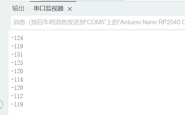 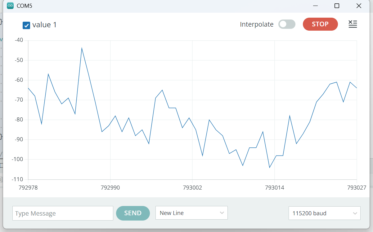 # 个人心得 本次开发板的任务对新手很友好,门槛也很低,我也是第一次玩开发板,通过阅读官方的开发文档也对该板子有一定的了解,感应器很多值得玩耍。 -#------------ 补充内容 (2025-1-21 22:53): 任务代码下载:https://download.eeworld.com.cn/detail/ShallGoing/635458 物料清单:ardunio rp2024 connect 板子及mirco usb数据线一根 补充内容 (2025-1-21 23:06): 流程图一: ```mermaid graph TD A[开始] --> B[初始化串口] B --> C[初始化 LED 引脚] C --> D[打印消息] D --> E[亮红灯] E --> F[等待 1 秒] F --> G[关红灯] G --> H[等待 1 秒]...
-
加入了学习《followme第四期结果展示》,观看 followme第二季第四期结果展示
-
上传了资料: followme第四期代码汇总
- 2024-12-27
-
加入了学习《直播回放: DigiKey FollowMe 第二季 第4期 Arduino Nano RP2040 Connect 任务讲解》,观看 Arduino Nano RP2040 Connect 任务讲解
- 2024-11-21
-
回复了主题帖: 入围名单公布:嵌入式工程师AI挑战营(进阶)的挑战者们,领取板卡啦
个人信息已确认,领取板卡,可继续完成任务。
- 2024-11-18
-
回复了主题帖: 嵌入式工程师AI挑战营(进阶):在RV1106部署InsightFace算法的多人实时人脸识别实战
跟帖申请; 申请理由: 我对人脸识别和嵌入式系统开发有浓厚的兴趣,希望通过在RV1106开发板上部署InsightFace算法,深入学习人工智能在嵌入式设备上的应用,实现技能的提升和知识的拓展。 了解的InsightFace及部署思路: InsightFace是一套基于深度学习的人脸分析工具,包括人脸检测、识别和表征等功能,具有高精度和高效率的特点。要在RV1106上部署InsightFace,可先将模型进行轻量化处理,如量化和剪枝,然后使用RV1106支持的推理引擎进行部署。通过优化算法和合理利用硬件加速,可以实现多人实时人脸识别。 计划部署的应用: 我计划在RV1106 Linux开发板上开发一套智能门禁系统,集成InsightFace的多人实时人脸识别功能。该系统可用于办公楼、小区等场景,实现对进出人员的快速识别和权限管理,提升安全性和便利性。
发布的帖子
统计信息
已有12人来访过
- 芯积分:28
- 好友:--
- 主题:1
- 回复:2
留言

现在还没有留言
推荐博文
- 频率计-拆机
- 加湿器如何实现液位提醒
- 【Follow me第二季第2期】Arduion UR4 作业提交
- 【Follow me第二季第2期】4.基础任务之 DAC/OPAM/ADC
- EMC测试基本环境要求 - 一汽轿车上汽SMTC 3 800 006—2015(V4)
- 【读书】《RISC-V 体系结构编程与实践(第2版)》-- 结构学习
- 《人工智能实践教程——从Python入门到机器学习》阅读分享一 安装和基本概念和api
- EMC测试基本环境要求 - PSA B21 7110
- 高集成智能硬件伺服电机驱控芯片TMC9660控制步进伺服电机静音高速驱动
- IP5407这个芯片,你们有遇到过休眠后唤不醒的吗?
- 拆解HT7183:16V, 4.5A异步DC-DC升压转换器芯片资料
- 数字隔离器,为智能家居构筑无干扰的“安全防线”
- 【Follow me第二季第4期】Arduino_Nano_Connect板子---任务3:驱动外设PDM麦克风
- OpenHarmony4如何添加默认应用?触觉智能瑞芯微RK3566鸿蒙开发板演示
- 刹车步进电机由什么构成?