�Լ�����վ����д���£�û�ж��ߣ�û�н����������������Ҹ��ط�ͬ�����²��ģ�����21ic���ܼ����ҵ���վ��ʽ�����Ծ��ҵ����ˣ�������ϣ��������������ջ�
һ��GPIO����
/**
* @brief ʹ��ADC1��DMA1��ʱ�ӣ���ʼ��PC.01
* @param ��
* @retval ��
*/
static void ADC1_GPIO_Config(void)
{
GPIO_InitTypeDef GPIO_InitStructure;
/* Enable DMA clock */
RCC_AHBPeriphClockCmd(RCC_AHBPeriph_DMA1, ENABLE);
/* Enable ADC1 and GPIOC clock */
RCC_APB2PeriphClockCmd(RCC_APB2Periph_ADC1 | RCC_APB2Periph_GPIOC, ENABLE);
/* Configure PC.01 as analog input */
GPIO_InitStructure.GPIO_Pin = GPIO_Pin_1;
GPIO_InitStructure.GPIO_Mode = GPIO_Mode_AIN;
GPIO_Init(GPIOC, &GPIO_InitStructure);// PC1,��Ϊ������ģʽ�����Բ�����������
}
RCC_AHBPeriphClockCmd(RCC_AHBPeriph_DMA1, ENABLE);
��ΪDMA1������AHB�����������Կ���AHBʱ�ӡ�
RCC_APB2PeriphClockCmd(RCC_APB2Periph_ADC1 | RCC_APB2Periph_GPIOC, ENABLE);
����ADC1��GPIOC��ʱ�ӣ�����������APB2��������
GPIO_InitStructure.GPIO_Pin = GPIO_Pin_1;
GPIO_InitStructure.GPIO_Mode = GPIO_Mode_AIN;
GPIO_Init(GPIOC, &GPIO_InitStructure);// PC1,��Ϊ������ģʽ�����Բ�����������
����ѡΪGPIOC->Pin1�ţ�IOģʽΪģ�����롣
��ΪPC1ΪADC1�ĵ�11����ͨ����������ѡ�����ͨ����ʵ��ADC���ܣ�����Ҫѡ��PC1������

����ͼ��֪��������ʹ��ADC����DAC���ܣ����������ž�Ӧ����Ϊģ��ģʽ���������ǽ�PC1����Ϊģ�����롣
�����ÿ⺯��GPIO_Init()��ʼ��GPIOC->Pin1�ţ�IO��������ϡ�
����ADC����
/**
* @brief ����ADC1�Ĺ���ģʽΪDMAģʽ
* @param ��
* @retval ��
*/
static void ADC1_Mode_Config(void)
{
DMA_InitTypeDef DMA_InitStructure;
ADC_InitTypeDef ADC_InitStructure;
/* DMA channel1 configuration */
DMA_DeInit(DMA1_Channel1);
DMA_InitStructure.DMA_PeripheralBaseAddr = ADC1_DR_Address; //ADC��ַ
DMA_InitStructure.DMA_MemoryBaseAddr = (u32)&ADC_ConvertedValue;//�ڴ��ַ
DMA_InitStructure.DMA_DIR = DMA_DIR_PeripheralSRC;
DMA_InitStructure.DMA_BufferSize = 1;
DMA_InitStructure.DMA_PeripheralInc = DMA_PeripheralInc_Disable;//�����ַ�̶�
DMA_InitStructure.DMA_MemoryInc = DMA_MemoryInc_Disable; //�ڴ��ַ�̶�
DMA_InitStructure.DMA_PeripheralDataSize = DMA_PeripheralDataSize_HalfWord;//����
DMA_InitStructure.DMA_MemoryDataSize = DMA_MemoryDataSize_HalfWord;
DMA_InitStructure.DMA_Mode = DMA_Mode_Circular;//ѭ������
DMA_InitStructure.DMA_Priority = DMA_Priority_High;
DMA_InitStructure.DMA_M2M = DMA_M2M_Disable;
DMA_Init(DMA1_Channel1, &DMA_InitStructure);
/* Enable DMA channel1 */
DMA_Cmd(DMA1_Channel1, ENABLE);
/* ADC1 configuration */
ADC_InitStructure.ADC_Mode = ADC_Mode_Independent;//����ADCģʽ
ADC_InitStructure.ADC_ScanConvMode = DISABLE ; //��ֹɨ��ģʽ��ɨ��ģʽ���ڶ�ͨ���ɼ�
ADC_InitStructure.ADC_ContinuousConvMode = ENABLE;//��������ת��ģʽ������ͣ�ؽ���ADCת��
ADC_InitStructure.ADC_ExternalTrigConv = ADC_ExternalTrigConv_None;//��ʹ���ⲿ����ת��
ADC_InitStructure.ADC_DataAlign = ADC_DataAlign_Right; //�ɼ������Ҷ���
ADC_InitStructure.ADC_NbrOfChannel = 1; //Ҫת����ͨ����Ŀ1
ADC_Init(ADC1, &ADC_InitStructure);
/*����ADCʱ�ӣ�ΪPCLK2��8��Ƶ����9MHz*/
RCC_ADCCLKConfig(RCC_PCLK2_Div8);
/*����ADC1��ͨ��11Ϊ55.5���������ڣ�����Ϊ1 */
ADC_RegularChannelConfig(ADC1, ADC_Channel_11, 1, ADC_SampleTime_55Cycles5);
/* Enable ADC1 DMA */
ADC_DMACmd(ADC1, ENABLE);
/* Enable ADC1 */
ADC_Cmd(ADC1, ENABLE);
/*��ʼ��У�Ĵ��� */
ADC_ResetCalibration(ADC1);
/*�ȴ�У�Ĵ�����ʼ����� */
while(ADC_GetResetCalibrationStatus(ADC1));
/* ADCУ */
ADC_StartCalibration(ADC1);
/* �ȴ�У���*/
while(ADC_GetCalibrationStatus(ADC1));
/* ����û�в����ⲿ����������ʹ����������ADCת�� */
ADC_SoftwareStartConvCmd(ADC1, ENABLE);
}
�ȶ���ṹ��ADC_InitStructure��������ΪADC_InitTypeDef����ԱΪADC������ã�ģʽ��ɨ��ת��������ת�����ⲿ���������ݶ��롢Ҫת����ͨ����Ŀ��
DMA_DeInit(DMA1_Channel1);
DMA1ͨ��1�IJ�����ʼ��Ϊȱʡֵ��
DMA�������Ķ������£�
#define ADC1_DR_Address ((u32)0x40012400+0x4c)
��ΪADC1�Ļ���ַΪ0x4001 2400���������ݼĴ�������ڻ���ַ��ƫ��Ϊ0x4c�����������ַΪ����֮�ͣ�0x4001 2400 + 0x4c����
__IO uint16_t ADC_ConvertedValue;
#define DMA_DIR_PeripheralSRC ((uint32_t)0x00000000)
#define DMA_PeripheralInc_Disable ((uint32_t)0x00000000)
#define DMA_MemoryInc_Disable ((uint32_t)0x00000000)
#define DMA_PeripheralDataSize_HalfWord ((uint32_t)0x00000100)
#define DMA_MemoryDataSize_HalfWord ((uint32_t)0x00000400)
#define DMA_Mode_Circular ((uint32_t)0x00000020)
#define DMA_Priority_High ((uint32_t)0x00002000)
#define DMA_M2M_Disable ((uint32_t)0x00000000)
������������ֵ��DMA���г�ʼ��
DMA_Init(DMA1_Channel1, &DMA_InitStructure);
DMA_Init()�����������£�
/**
* @brief Initializes the DMAy Channelx according to the specified
* parameters in the DMA_InitStruct.
* @param DMAy_Channelx: where y can be 1 or 2 to select the DMA and
* x can be 1 to 7 for DMA1 and 1 to 5 for DMA2 to select the DMA Channel.
* @param DMA_InitStruct: pointer to a DMA_InitTypeDef structure that
* contains the configuration information for the specified DMA Channel.
* @retval None
*/
void DMA_Init(DMA_Channel_TypeDef* DMAy_Channelx, DMA_InitTypeDef* DMA_InitStruct)
{
uint32_t tmpreg = 0;
/* Check the parameters */
assert_param(IS_DMA_ALL_PERIPH(DMAy_Channelx));
assert_param(IS_DMA_DIR(DMA_InitStruct->DMA_DIR));
assert_param(IS_DMA_BUFFER_SIZE(DMA_InitStruct->DMA_BufferSize));
assert_param(IS_DMA_PERIPHERAL_INC_STATE(DMA_InitStruct->DMA_PeripheralInc));
assert_param(IS_DMA_MEMORY_INC_STATE(DMA_InitStruct->DMA_MemoryInc));
assert_param(IS_DMA_PERIPHERAL_DATA_SIZE(DMA_InitStruct->DMA_PeripheralDataSize));
assert_param(IS_DMA_MEMORY_DATA_SIZE(DMA_InitStruct->DMA_MemoryDataSize));
assert_param(IS_DMA_MODE(DMA_InitStruct->DMA_Mode));
assert_param(IS_DMA_PRIORITY(DMA_InitStruct->DMA_Priority));
assert_param(IS_DMA_M2M_STATE(DMA_InitStruct->DMA_M2M));
/*--------------------------- DMAy Channelx CCR Configuration -----------------*/
/* Get the DMAy_Channelx CCR value */
tmpreg = DMAy_Channelx->CCR;
/* Clear MEM2MEM, PL, MSIZE, PSIZE, MINC, PINC, CIRC and DIR bits */
tmpreg &= CCR_CLEAR_Mask;
/* Configure DMAy Channelx: data transfer, data size, priority level and mode */
/* Set DIR bit according to DMA_DIR value */
/* Set CIRC bit according to DMA_Mode value */
/* Set PINC bit according to DMA_PeripheralInc value */
/* Set MINC bit according to DMA_MemoryInc value */
/* Set PSIZE bits according to DMA_PeripheralDataSize value */
/* Set MSIZE bits according to DMA_MemoryDataSize value */
/* Set PL bits according to DMA_Priority value */
/* Set the MEM2MEM bit according to DMA_M2M value */
tmpreg |= DMA_InitStruct->DMA_DIR | DMA_InitStruct->DMA_Mode |
DMA_InitStruct->DMA_PeripheralInc | DMA_InitStruct->DMA_MemoryInc |
DMA_InitStruct->DMA_PeripheralDataSize | DMA_InitStruct->DMA_MemoryDataSize |
DMA_InitStruct->DMA_Priority | DMA_InitStruct->DMA_M2M;
/* Write to DMAy Channelx CCR */
DMAy_Channelx->CCR = tmpreg;
/*--------------------------- DMAy Channelx CNDTR Configuration ---------------*/
/* Write to DMAy Channelx CNDTR */
DMAy_Channelx->CNDTR = DMA_InitStruct->DMA_BufferSize;
/*--------------------------- DMAy Channelx CPAR Configuration ----------------*/
/* Write to DMAy Channelx CPAR */
DMAy_Channelx->CPAR = DMA_InitStruct->DMA_PeripheralBaseAddr;
/*--------------------------- DMAy Channelx CMAR Configuration ----------------*/
/* Write to DMAy Channelx CMAR */
DMAy_Channelx->CMAR = DMA_InitStruct->DMA_MemoryBaseAddr;
}
tmpreg = DMAy_Channelx->CCR;
��tmpreg = 0;
tmpreg &= CCR_CLEAR_Mask;
0�����κ����Ծ�Ϊ0������tmpreg = 0;
tmpreg |= DMA_InitStruct->DMA_DIR | DMA_InitStruct->DMA_Mode |
DMA_InitStruct->DMA_PeripheralInc | DMA_InitStruct->DMA_MemoryInc |
DMA_InitStruct->DMA_PeripheralDataSize | DMA_InitStruct->DMA_MemoryDataSize |
DMA_InitStruct->DMA_Priority | DMA_InitStruct->DMA_M2M;
��temreg = 0 | 0x0000 0000 | 0x0000 0020 | 0x0000 0000 | 0x0000 0000 | 0x0000 0100 | 0x0000 0400 | 0x0000 2000 | 0x0000 0000 = 0x0000 2520;
DMAy_Channelx->CCR = tmpreg;
��DMA1_Channel1->CCR = 0x0000 2520;��DMA��CCR�Ĵ�������

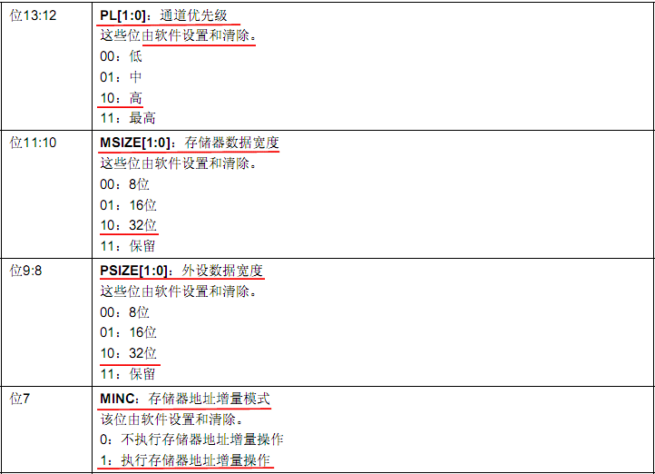
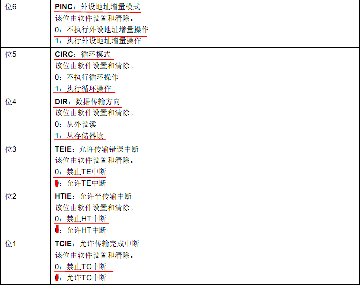

��֪��DMA1��ͨ��1������Ϊ���Ǵ洢�����洢��ģʽ��ͨ�����ȼ�Ϊ�ߡ��洢�����ݿ���Ϊ16λ���������ݿ���Ϊ16λ����ִ�д洢����ַ������������ִ�������ַ����������ִ��ѭ�����������������������Ϊ����Դ����
DMA_Cmd(DMA1_Channel1, ENABLE);
ʹ��DMA1ͨ��1������˵��һ�£�ADC1��DMA������ͨ��DMA1��ͨ��1��ʵ�ֵ�������ɲο�DMA����ӳ��ͼ����
ADC�������Ķ������£�
#define ADC_Mode_Independent ((uint32_t)0x00000000)
typedef enum {DISABLE = 0, ENABLE = !DISABLE} FunctionalState;
#define ADC_ExternalTrigConv_None ((uint32_t)0x000E0000) /*!< For ADC1, ADC2 and ADC3 */
#define ADC_DataAlign_Right ((uint32_t)0x00000000)
������������ֵ��ADC���г�ʼ����
ADC_Init(ADC1, &ADC_InitStructure);
�⺯��ADC_Init()�Ķ������£�
/**
* @brief Initializes the ADCx peripheral according to the specified parameters
* in the ADC_InitStruct.
* @param ADCx: where x can be 1, 2 or 3 to select the ADC peripheral.
* @param ADC_InitStruct: pointer to an ADC_InitTypeDef structure that contains
* the configuration information for the specified ADC peripheral.
* @retval None
*/
void ADC_Init(ADC_TypeDef* ADCx, ADC_InitTypeDef* ADC_InitStruct)
{
uint32_t tmpreg1 = 0;
uint8_t tmpreg2 = 0;
/* Check the parameters */
assert_param(IS_ADC_ALL_PERIPH(ADCx));
assert_param(IS_ADC_MODE(ADC_InitStruct->ADC_Mode));
assert_param(IS_FUNCTIONAL_STATE(ADC_InitStruct->ADC_ScanConvMode));
assert_param(IS_FUNCTIONAL_STATE(ADC_InitStruct->ADC_ContinuousConvMode));
assert_param(IS_ADC_EXT_TRIG(ADC_InitStruct->ADC_ExternalTrigConv));
assert_param(IS_ADC_DATA_ALIGN(ADC_InitStruct->ADC_DataAlign));
assert_param(IS_ADC_REGULAR_LENGTH(ADC_InitStruct->ADC_NbrOfChannel));
/*---------------------------- ADCx CR1 Configuration -----------------*/
/* Get the ADCx CR1 value */
tmpreg1 = ADCx->CR1;
/* Clear DUALMOD and SCAN bits */
tmpreg1 &= CR1_CLEAR_Mask;
/* Configure ADCx: Dual mode and scan conversion mode */
/* Set DUALMOD bits according to ADC_Mode value */
/* Set SCAN bit according to ADC_ScanConvMode value */
tmpreg1 |= (uint32_t)(ADC_InitStruct->ADC_Mode | ((uint32_t)ADC_InitStruct->ADC_ScanConvMode << 8));
/* Write to ADCx CR1 */
ADCx->CR1 = tmpreg1;
/*---------------------------- ADCx CR2 Configuration -----------------*/
/* Get the ADCx CR2 value */
tmpreg1 = ADCx->CR2;
/* Clear CONT, ALIGN and EXTSEL bits */
tmpreg1 &= CR2_CLEAR_Mask;
/* Configure ADCx: external trigger event and continuous conversion mode */
/* Set ALIGN bit according to ADC_DataAlign value */
/* Set EXTSEL bits according to ADC_ExternalTrigConv value */
/* Set CONT bit according to ADC_ContinuousConvMode value */
tmpreg1 |= (uint32_t)(ADC_InitStruct->ADC_DataAlign | ADC_InitStruct->ADC_ExternalTrigConv |
((uint32_t)ADC_InitStruct->ADC_ContinuousConvMode << 1));
/* Write to ADCx CR2 */
ADCx->CR2 = tmpreg1;
/*---------------------------- ADCx SQR1 Configuration -----------------*/
/* Get the ADCx SQR1 value */
tmpreg1 = ADCx->SQR1;
/* Clear L bits */
tmpreg1 &= SQR1_CLEAR_Mask;
/* Configure ADCx: regular channel sequence length */
/* Set L bits according to ADC_NbrOfChannel value */
tmpreg2 |= (uint8_t) (ADC_InitStruct->ADC_NbrOfChannel - (uint8_t)1);
tmpreg1 |= (uint32_t)tmpreg2 << 20;
/* Write to ADCx SQR1 */
ADCx->SQR1 = tmpreg1;
}
tmpreg1 = ADCx->CR1;
��tmpreg1 = 0;
tmpreg1 &= CR1_CLEAR_Mask;
0�����κ�����Ϊ0������tmpreg1 = 0;
tmpreg1 |= (uint32_t)(ADC_InitStruct->ADC_Mode | ((uint32_t)ADC_InitStruct->ADC_ScanConvMode << 8));
��tmpreg1 = 0 | (0x0000 0000) | (0 << 8) = 0;
ADCx->CR1 = tmpreg1;
��ADC1->CR1 = 0;��ADC��CR1�Ĵ�������

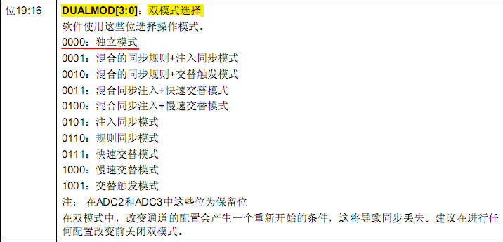

��֪��ADC1������Ϊ������ģʽ���ر�ɨ��ģʽ��
tmpreg1 = ADCx->CR2;
��tmpreg1 = 0;
tmpreg1 &= CR2_CLEAR_Mask;
��tmpreg1 = 0;
tmpreg1 |= (uint32_t)(ADC_InitStruct->ADC_DataAlign | ADC_InitStruct->ADC_ExternalTrigConv |
((uint32_t)ADC_InitStruct->ADC_ContinuousConvMode << 1));
��tmpreg1 = 0 | 0x0000 0000 | 0x000E 0000 | (0x01 << 1) = 0x000E 0002;
ADCx->CR2 = tmpreg1;
��ADC1->CR2 = 0x000E 0002;��ADC��CR2�Ĵ�������


��֪��ADC1������Ϊ��ѡ��SWSTARTΪ�����¼�������ת��ģʽ��
tmpreg1 = ADCx->SQR1;
��tmpreg1 = 0;
tmpreg1 &= SQR1_CLEAR_Mask;
��tmpreg1 = 0;
tmpreg2 |= (uint8_t) (ADC_InitStruct->ADC_NbrOfChannel - (uint8_t)1);
��tmpreg2 = 0 | (1 - 1) = 0;
tmpreg1 |= (uint32_t)tmpreg2 << 20;
��tmpreg1 = 0 | (0 << 20) = 0;
ADCx->SQR1 = tmpreg1;
��ADC1->SQR1 = 0;��ADC��SQR1�Ĵ�������
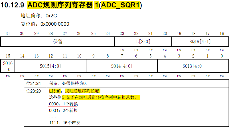
��֪��ADC1������Ϊ��1��ת����
RCC_ADCCLKConfig(RCC_PCLK2_Div8);
/**
* @brief Configures the ADC clock (ADCCLK).
* @param RCC_PCLK2: defines the ADC clock divider. This clock is derived from
* the APB2 clock (PCLK2).
* This parameter can be one of the following values:
* @arg RCC_PCLK2_Div2: ADC clock = PCLK2/2
* @arg RCC_PCLK2_Div4: ADC clock = PCLK2/4
* @arg RCC_PCLK2_Div6: ADC clock = PCLK2/6
* @arg RCC_PCLK2_Div8: ADC clock = PCLK2/8
* @retval None
*/
void RCC_ADCCLKConfig(uint32_t RCC_PCLK2)
{
uint32_t tmpreg = 0;
/* Check the parameters */
assert_param(IS_RCC_ADCCLK(RCC_PCLK2));
tmpreg = RCC->CFGR;
/* Clear ADCPRE[1:0] bits */
tmpreg &= CFGR_ADCPRE_Reset_Mask;
/* Set ADCPRE[1:0] bits according to RCC_PCLK2 value */
tmpreg |= RCC_PCLK2;
/* Store the new value */
RCC->CFGR = tmpreg;
}
��������RCC_ADCCLKConfig()�������弰Debug����
�ɵã�RCC->CFGR = 0x001D C40A;��RCC��CFGR�Ĵ�������


��֪��ADCʱ�ӱ�����Ϊ��PCLK2��8��Ƶ��72 / 8 = 9 MHz����
ADC_RegularChannelConfig(ADC1, ADC_Channel_11, 1, ADC_SampleTime_55Cycles5);
ADC_RegularChannelConfig()�����������£�
void ADC_RegularChannelConfig(ADC_TypeDef* ADCx, uint8_t ADC_Channel, uint8_t Rank, uint8_t ADC_SampleTime)
{
uint32_t tmpreg1 = 0, tmpreg2 = 0;
/* Check the parameters */
assert_param(IS_ADC_ALL_PERIPH(ADCx));
assert_param(IS_ADC_CHANNEL(ADC_Channel));
assert_param(IS_ADC_REGULAR_RANK(Rank));
assert_param(IS_ADC_SAMPLE_TIME(ADC_SampleTime));
/* if ADC_Channel_10 ... ADC_Channel_17 is selected */
if (ADC_Channel > ADC_Channel_9)
{
/* Get the old register value */
tmpreg1 = ADCx->SMPR1;
/* Calculate the mask to clear */
tmpreg2 = SMPR1_SMP_Set << (3 * (ADC_Channel - 10));
/* Clear the old channel sample time */
tmpreg1 &= ~tmpreg2;
/* Calculate the mask to set */
tmpreg2 = (uint32_t)ADC_SampleTime << (3 * (ADC_Channel - 10));
/* Set the new channel sample time */
tmpreg1 |= tmpreg2;
/* Store the new register value */
ADCx->SMPR1 = tmpreg1;
}
else /* ADC_Channel include in ADC_Channel_[0..9] */
{
/* Get the old register value */
tmpreg1 = ADCx->SMPR2;
/* Calculate the mask to clear */
tmpreg2 = SMPR2_SMP_Set << (3 * ADC_Channel);
/* Clear the old channel sample time */
tmpreg1 &= ~tmpreg2;
/* Calculate the mask to set */
tmpreg2 = (uint32_t)ADC_SampleTime << (3 * ADC_Channel);
/* Set the new channel sample time */
tmpreg1 |= tmpreg2;
/* Store the new register value */
ADCx->SMPR2 = tmpreg1;
}
/* For Rank 1 to 6 */
if (Rank < 7)
{
/* Get the old register value */
tmpreg1 = ADCx->SQR3;
/* Calculate the mask to clear */
tmpreg2 = SQR3_SQ_Set << (5 * (Rank - 1));
/* Clear the old SQx bits for the selected rank */
tmpreg1 &= ~tmpreg2;
/* Calculate the mask to set */
tmpreg2 = (uint32_t)ADC_Channel << (5 * (Rank - 1));
/* Set the SQx bits for the selected rank */
tmpreg1 |= tmpreg2;
/* Store the new register value */
ADCx->SQR3 = tmpreg1;
}
/* For Rank 7 to 12 */
else if (Rank < 13)
{
/* Get the old register value */
tmpreg1 = ADCx->SQR2;
/* Calculate the mask to clear */
tmpreg2 = SQR2_SQ_Set << (5 * (Rank - 7));
/* Clear the old SQx bits for the selected rank */
tmpreg1 &= ~tmpreg2;
/* Calculate the mask to set */
tmpreg2 = (uint32_t)ADC_Channel << (5 * (Rank - 7));
/* Set the SQx bits for the selected rank */
tmpreg1 |= tmpreg2;
/* Store the new register value */
ADCx->SQR2 = tmpreg1;
}
/* For Rank 13 to 16 */
else
{
/* Get the old register value */
tmpreg1 = ADCx->SQR1;
/* Calculate the mask to clear */
tmpreg2 = SQR1_SQ_Set << (5 * (Rank - 13));
/* Clear the old SQx bits for the selected rank */
tmpreg1 &= ~tmpreg2;
/* Calculate the mask to set */
tmpreg2 = (uint32_t)ADC_Channel << (5 * (Rank - 13));
/* Set the SQx bits for the selected rank */
tmpreg1 |= tmpreg2;
/* Store the new register value */
ADCx->SQR1 = tmpreg1;
}
}
Debug���Եã�
ADC1->SMPR1 = 0x0000 0028;��SMPR1�Ĵ�������
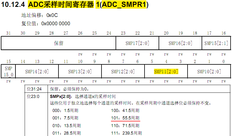
��֪��ADC1������Ϊ������ʱ��Ϊ55.5��������
ADC1->SQR3 = 0x0000 000B;��SQR3�Ĵ�������

��֪��ADC1������Ϊ�����������еĵ�1��ת����
ADC_DMACmd(ADC1, ENABLE);
ADC_Cmd(ADC1, ENABLE);
ʹ��ADC1��DMAģʽ��ʹ��ADC1��
/*��ʼ��У�Ĵ��� */
ADC_ResetCalibration(ADC1);
/*�ȴ�У�Ĵ�����ʼ����� */
while(ADC_GetResetCalibrationStatus(ADC1));
/* ADCУ */
ADC_StartCalibration(ADC1);
/* �ȴ�У���*/
while(ADC_GetCalibrationStatus(ADC1));
ע�����ڿ�ʼADCת��֮ǰ�������ADC����У�����漴ΪУ����������ƪ��������ϸ���ܡ�
ADC_SoftwareStartConvCmd(ADC1, ENABLE);
ADC_SoftwareStartConvCmd()�����������£�
void ADC_SoftwareStartConvCmd(ADC_TypeDef* ADCx, FunctionalState NewState)
{
/* Check the parameters */
assert_param(IS_ADC_ALL_PERIPH(ADCx));
assert_param(IS_FUNCTIONAL_STATE(NewState));
if (NewState != DISABLE)
{
/* Enable the selected ADC conversion on external event and start the selected
ADC conversion */
ADCx->CR2 |= CR2_EXTTRIG_SWSTART_Set;
}
else
{
/* Disable the selected ADC conversion on external event and stop the selected
ADC conversion */
ADCx->CR2 &= CR2_EXTTRIG_SWSTART_Reset;
}
}
��ADC1->CR2 = 0x005E 0103������ĵ��Խ��(0x001E 0103)�Ҿ��������⣬ǰ�������Լ��Ľ����������CR2����


��֪��ADC1������Ϊ��ʹ���ⲿ�����ź�����ת������ʼת������ͨ����
ADC_ConvertedValueLocal =(float) ADC_ConvertedValue/4096*3.3;
�������ADת���Ľ���������Բο���ѹֵ��������3.3V��Ϊһ����λ������3.3V�ȷֳ�4096�����������
ע����
ADC�����ѹ��Χ��VREF- <= VIN <= VREF+
VREF+��ѹ��Χ�� 2.4V <= VREF+ <= VDDA
VDDA��ѹ��Χ�� 2.4V <= VDDA <= VDD(3.6V)
�ʣ�ADC�����ѹ��߲�����3.6V��
����Ϊֹ��STM32��ADC���ܾ���������ˣ����ǿ��ԶԴ�PC1������ĵ�ѹ���в�����ͨ�����ڻ�LCD����ʾ��ѹ�ľ�����ֵ���ɲ�����ѹ��Χ��0 ~ 3.3V����
��������ѧʶ���ޣ����еĴ�����©֮�������������ָ����
ԭ����Ʒ


