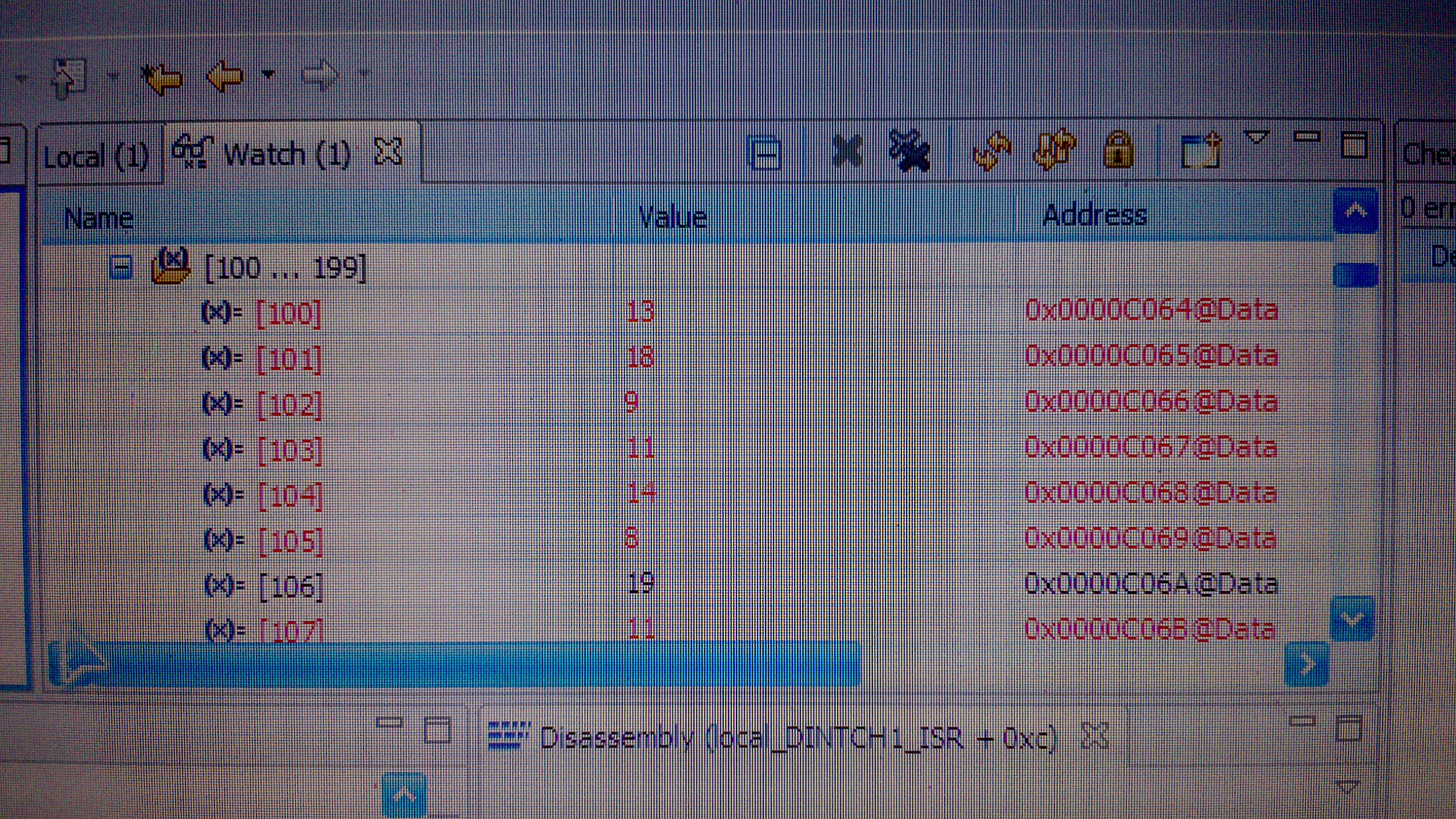
�������ĵ���һֱ�㵽���ϰ˵㣬���ڰ�DMA���䷽ʽ�ɼ�AD���ݵ�Դ����㶨�ˡ��������Ǵ�������ҵ�Ӣ��ˮƽ�ţ�˵����Ҳ��һ�����Ĵ���û���úõ��¶���������������仯�������ǣ��о�����ʾ�����Ѿ����Ҳ�Զ�ˣ�������

���Ĵ��룺������
�����ŷ��֣����Ĵ��뱻��˾���Ը������ˣ��Ժ�ֱ�����������ˣ���Ȼ�е㳤������
#include \"DSP28x_Project.h\" // Device Headerfile and Examples Include File
// ADC start parameters
#if (CPU_FRQ_150MHZ) // Default - 150 MHz SYSCLKOUT
#define ADC_MODCLK 0x3 // HSPCLK = SYSCLKOUT/2*ADC_MODCLK2 = 150/(2*3) = 25.0 MHz
#endif
#if (CPU_FRQ_100MHZ)
#define ADC_MODCLK 0x2 // HSPCLK = SYSCLKOUT/2*ADC_MODCLK2 = 100/(2*2) = 25.0 MHz
#endif
#define ADC_CKPS 0x0 // ADC module clock = HSPCLK/1 = 25.5MHz/(1) = 25.0 MHz
#define ADC_SHCLK 0x1 // S/H width in ADC module periods = 2 ADC cycle
#define BUF_SIZE 1024 // Sample buffer size
#pragma DATA_SECTION(DMABuf1,\"DMARAML4\");
volatile Uint16 DMABuf1[BUF_SIZE];
volatile Uint16 *DMADest;
volatile Uint16 *DMASource;
interrupt void local_DINTCH1_ISR(void);
void main(void)
{
Uint16 i;
// Step 1. Initialize System Control:
// PLL, WatchDog, enable Peripheral Clocks
// This example function is found in the DSP2833x_SysCtrl.c file.
InitSysCtrl();
// Specific clock setting for this example:
EALLOW;
SysCtrlRegs.HISPCP.all = ADC_MODCLK; // HSPCLK = SYSCLKOUT/ADC_MODCLK
EDIS;
// Step 2. Initialize GPIO:
// This example function is found in the DSP2833x_Gpio.c file and
// illustrates how to set the GPIO to it\'s default state.
// InitGpio(); // Skipped for this example
// Step 3. Clear all interrupts and initialize PIE vector table:
// Disable CPU interrupts
DINT;
// Initialize the PIE control registers to their default state.
// The default state is all PIE interrupts disabled and flags
// are cleared.
// This function is found in the DSP2833x_PieCtrl.c file.
InitPieCtrl();
// Disable CPU interrupts and clear all CPU interrupt flags:
IER = 0x0000;
IFR = 0x0000;
// Initialize the PIE vector table with pointers to the shell Interrupt
// Service Routines (ISR).
// This will populate the entire table, even if the interrupt
// is not used in this example. This is useful for debug purposes.
// The shell ISR routines are found in DSP2833x_DefaultIsr.c.
// This function is found in DSP2833x_PieVect.c.
InitPieVectTable();
// Interrupts that are used in this example are re-mapped to
// ISR functions found within this file.
EALLOW; // Allow access to EALLOW protected registers
PieVectTable.DINTCH1= &local_DINTCH1_ISR;
EDIS; // Disable access to EALLOW protected registers
IER = M_INT7 ; //Enable INT7 (7.1 DMA Ch1)
EnableInterrupts();
// Step 4. Initialize all the Device Peripherals:
// This function is found in DSP2833x_InitPeripherals.c
// InitPeripherals(); // Not required for this example
InitAdc(); // For this example, init the ADC
// Specific ADC setup for this example:
AdcRegs.ADCTRL1.bit.ACQ_PS = ADC_SHCLK; // Sequential mode: Sample rate = 1/[(2+ACQ_PS)*ADC clock in ns]
// = 1/(3*40ns) =8.3MHz (for 150 MHz SYSCLKOUT)
// = 1/(3*80ns) =4.17MHz (for 100 MHz SYSCLKOUT)
// If Simultaneous mode enabled: Sample rate = 1/[(3+ACQ_PS)*ADC clock in ns]
AdcRegs.ADCTRL3.bit.ADCCLKPS = ADC_CKPS;
AdcRegs.ADCTRL1.bit.SEQ_CASC = 1; // 1 Cascaded mode
AdcRegs.ADCCHSELSEQ1.bit.CONV00 = 0x0;
AdcRegs.ADCTRL1.bit.CONT_RUN = 1; // Setup continuous run
AdcRegs.ADCTRL2.bit.INT_ENA_SEQ1 = 1; // Enable SEQ1 interrupt (every EOS)
AdcRegs.ADCTRL2.bit.RST_SEQ1 = 0x1;
AdcRegs.ADCTRL1.bit.SEQ_OVRD =1; // Enable Sequencer override feature
AdcRegs.ADCCHSELSEQ1.all = 0x0; // Initialize all ADC channel selects to A0
AdcRegs.ADCCHSELSEQ2.all = 0x0;
AdcRegs.ADCCHSELSEQ3.all = 0x0;
AdcRegs.ADCCHSELSEQ4.all = 0x0;
AdcRegs.ADCMAXCONV.bit.MAX_CONV1 = 0xf; // convert and store in 8 results registers
//Step 5. User specific code, enable interrupts:
// Initialize DMA
DMAInitialize();
// Clear Table
for (i=0; i
{
DMABuf1
= 0;
}
// Configure DMA Channel
DMADest = &DMABuf1[0]; //Point DMA destination to the beginning of the array
DMASource = &AdcMirror.ADCRESULT0; //Point DMA source to ADC result register base
DMACH1AddrConfig(DMADest,DMASource);
DMACH1BurstConfig(15,1,1);
DMACH1TransferConfig(63,-15,0);
DMACH1WrapConfig(66,0,66,16);
DMACH1ModeConfig(DMA_SEQ1INT,PERINT_ENABLE,ONESHOT_DISABLE,CONT_ENABLE,SYNC_DISABLE,SYNC_SRC,
OVRFLOW_DISABLE,SIXTEEN_BIT,CHINT_END,CHINT_ENABLE);
StartDMACH1();
// Start SEQ1
AdcRegs.ADCTRL2.bit.SOC_SEQ1 = 0x1;
for(;;)
{
/*for(i=0;i<10;i++){
for(j=0;j<1000;j++){}
AdcRegs.ADCTRL2.bit.SOC_SEQ1 = 1; //Normally ADC will be tied to ePWM, or timed routine
} //For this example will re-start manually*/
/*for(i=0;i<1024;i++)
{
while (AdcRegs.ADCST.bit.INT_SEQ1== 0) {} // Wait for interrupt
AdcRegs.ADCST.bit.INT_SEQ1_CLR = 1;
DMABuf1 =((AdcRegs.ADCRESULT0>>4) );
}*/
}
}
// INT7.1
interrupt void local_DINTCH1_ISR(void) // DMA Channel 1
{
// To receive more interrupts from this PIE group, acknowledge this interrupt
PieCtrlRegs.PIEACK.all = PIEACK_GROUP7;
// Next two lines for debug only to halt the processor here
// Remove after inserting ISR Code
asm (\" ESTOP0\");
// for(;;);
}���ĺ���������̳�ĸ�����ͼƬ����鿴ԭ��������
