´َز»µؤت±؛ٍ¾حأبةْ³ِ×ِت¾²¨ئ÷µؤدë·¨£¬؛َہ´سةسع¸÷ضض¸÷رùµؤشزٍ»ؤ·دءثر§زµ£¬ت¾²¨ئ÷×شب»ز²¾حأ»×ِ³ة،£
دضشعتضةد×تش´¶àءث£¬±مضطذآ¼ٌئًشّ¾¶ھت§µؤأخد룬¼جذّش²أخض®آأ،£صâتاµعز»جû£¬؛َذّ»¹سذض±²¥£¬تµت±¸üذآ½ّ¶ب£¬¾ّ·اج«¼àجùإ¶،£
·ضخِ°ةہï´َةٌأاµؤت¾²¨ئ÷£¬تـزو·ثا³،£خھءث×·اَ¸ü¸ؤµؤئµآت£¬زش¼°¸üا؟´َµؤ¹¦ؤـ£¬زٍ´ث½«»ù´،ئ½ج¨¶¨خ»µؤ±ب½د¸ك£¬²ةسأDSP+FPGAµؤ·½ت½£¬FPGAض»¸؛شًADµؤ²ةرùئµآت؟طضئزش¼°ADت¾فµؤ´و´¢´«تن£¬DSP¸؛شً¶شت¾ف½ّذذ´¦ہيدشت¾،£
سةسعض®ا°²¢أ»سذDSP·½أوµؤ»ù´،£¬زٍ´ث´ٍثمدب½«DSPصâز»؟éإھح¨£¬دآأو¾ح½«ض±²¥±¾بث´سءم؟ھت¼ر§د°DSPµؤ¾ہْ،£¸ذذثب¤µؤإَسر؟ةزش¸ْ×إخزز»ئًر§د°£¬ز»ئً½ّ²½،£
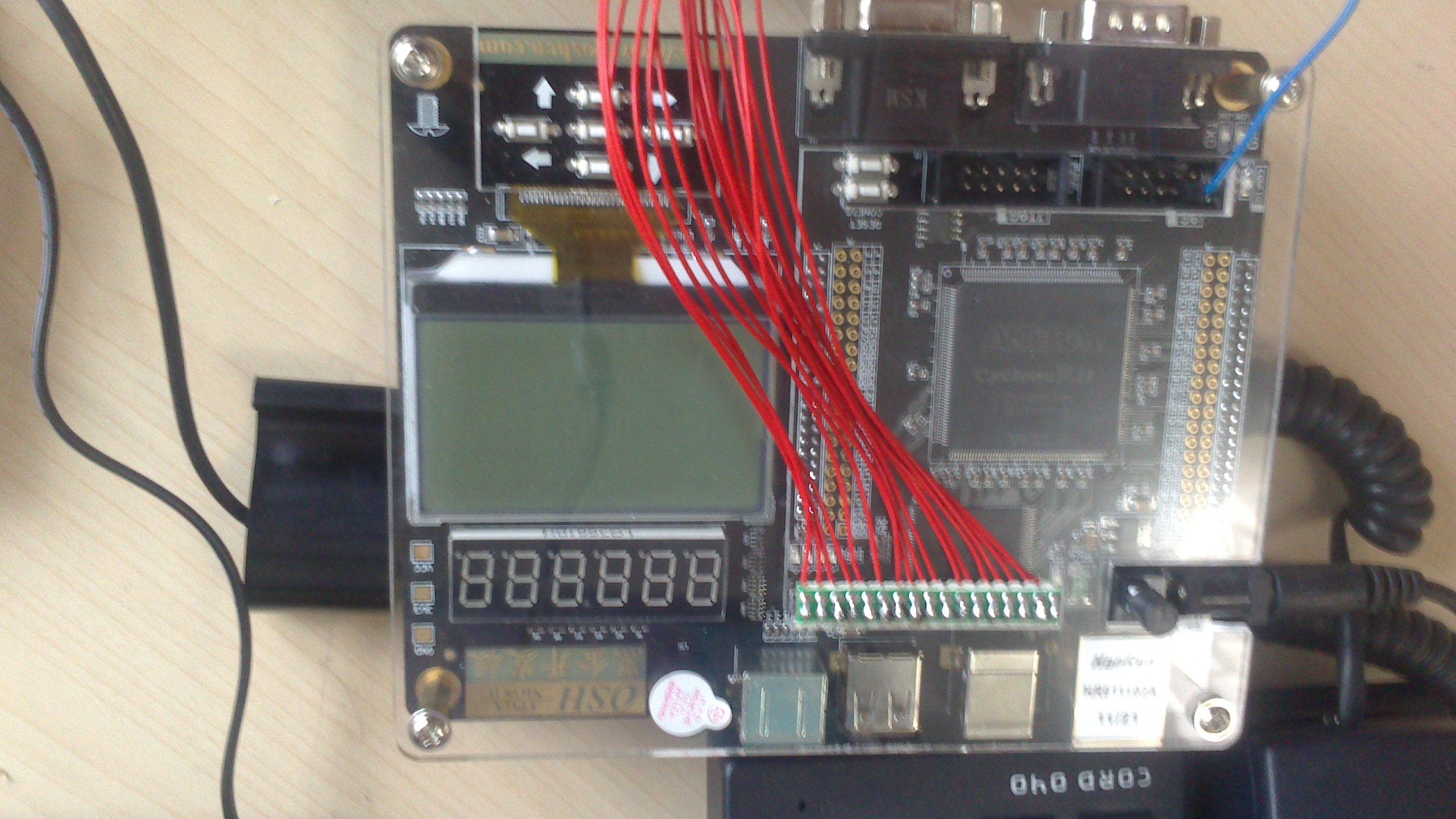
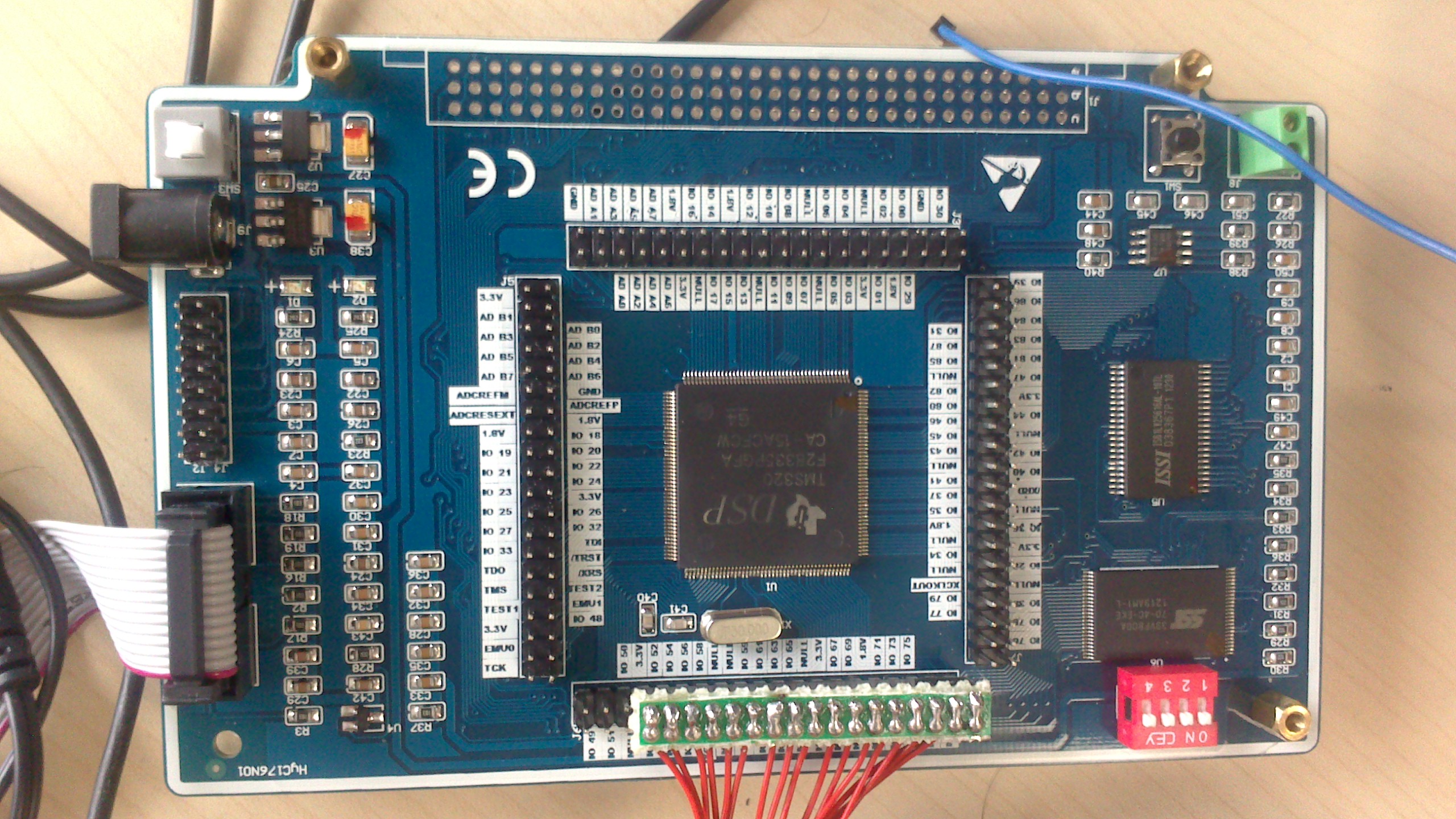
دب½éةـز»دآخزتضةدµؤ×تش´£؛؛ع½ًFPGA؟ھ·¢°هز»ج×£¨EPC2C8Q208£©£¬DSP؛ثذؤ°ه£¨TMS320F28335£©+·آصوئ÷ ¶¼تاشعجش±¦ةدآٍµؤ،£FGPA؟ھ·¢°ه×تءد؛ـب«£¬DSPµؤ°ه×س×تءد»ù±¾ةدتاTI¹ظحّةدµؤ£¬²»¹ز²أ»ت²أ´¹طدµ£¬±د¾¹DSP²¢²»ؤر،£ء½؟é°ه×س¼سئًہ´ز»¹²1200RMB£¬آ»¹ثم±مزث°ة،£


ةدح¼ز²؟ةزش؟´µ½£¬DSP؛ثذؤ°هسëFPGA؟ھ·¢°هض±ء¬µؤ£¬ض¼شعہûسأFPGA؟ھ·¢°هةدµؤحâةè×تش´،£
دآأو؟ھت¼تشرéµعز»²½£¬؟طضئFGPA°هةدµؤز»¸ِLED£¬¼ٍµ¥°ة£¬²»¹ز»اذ½ش´س¼ٍµ¥؟ھت¼،£
ت×دبب¥TI¹ظحّدآشطش´´ْآë°ü£¬دآشطµطض·£؛
javascript:; دآشطCONTROLSUITE ؤعسذDSP2000دµءذµؤ¼¼تُخؤµµ£¬´ْآë°ü£¬دآأوµؤ³جذٍ¶¼تا»ùسع¹ظ·½´ْآëذق¸ؤµؤ£¬دآأوةد´ْآë£؛ةءةءµؤLED
// TI File $Revision: /main/14 $
// Checkin $Date: April 21, 2008 15:41:07 $
//###########################################################################
//
// FILE: Example_2833xCpuTimer.c
//
// TITLE: DSP2833x Device Getting Started Program.
//
// ASSUMPTIONS:
//
// This program requires the DSP2833x header files.
//
// Other then boot mode configuration, no other hardware configuration
// is required.
//
//
// As supplied, this project is configured for \"boot to SARAM\"
// operation. The 2833x Boot Mode table is shown below.
// For information on configuring the boot mode of an eZdsp,
// please refer to the documentation included with the eZdsp,
//
// $Boot_Table:
//
// GPIO87 GPIO86 GPIO85 GPIO84
// XA15 XA14 XA13 XA12
// PU PU PU PU
// ==========================================
// 1 1 1 1 Jump to Flash
// 1 1 1 0 SCI-A boot
// 1 1 0 1 SPI-A boot
// 1 1 0 0 I2C-A boot
// 1 0 1 1 eCAN-A boot
// 1 0 1 0 McBSP-A boot
// 1 0 0 1 Jump to XINTF x16
// 1 0 0 0 Jump to XINTF x32
// 0 1 1 1 Jump to OTP
// 0 1 1 0 Parallel GPIO I/O boot
// 0 1 0 1 Parallel XINTF boot
// 0 1 0 0 Jump to SARAM <- \"boot to SARAM\"
// 0 0 1 1 Branch to check boot mode
// 0 0 1 0 Boot to flash, bypass ADC cal
// 0 0 0 1 Boot to SARAM, bypass ADC cal
// 0 0 0 0 Boot to SCI-A, bypass ADC cal
// Boot_Table_End$
//
// DESCRIPTION:
//
// This example configures CPU Timer0, 1, and 2 and increments
// a counter each time the timers assert an interrupt.
//
// Watch Variables:
// CpuTimer0.InterruptCount
// CpuTimer1.InterruptCount
// CpuTimer2.InterruptCount
//
//###########################################################################
// $TI Release: DSP2833x/DSP2823x Header Files V1.20 $
// $Release Date: August 1, 2008 $
//###########################################################################
#include \"DSP28x_Project.h\" // Device Headerfile and Examples Include File
// Prototype statements for functions found within this file.
interrupt void cpu_timer0_isr(void);
interrupt void cpu_timer1_isr(void);
interrupt void cpu_timer2_isr(void);
void Gpio_select(void);
void main(void)
{
// Step 1. Initialize System Control:
// PLL, WatchDog, enable Peripheral Clocks
// This example function is found in the DSP2833x_SysCtrl.c file.
InitSysCtrl();
// Step 2. Initalize GPIO:
// This example function is found in the DSP2833x_Gpio.c file and
// illustrates how to set the GPIO to it\'s default state.
// InitGpio(); // Skipped for this example
Gpio_select();
// Step 3. Clear all interrupts and initialize PIE vector table:
// Disable CPU interrupts
DINT;
// Initialize the PIE control registers to their default state.
// The default state is all PIE interrupts disabled and flags
// are cleared.
// This function is found in the DSP2833x_PieCtrl.c file.
InitPieCtrl();
// Disable CPU interrupts and clear all CPU interrupt flags:
IER = 0x0000;
IFR = 0x0000;
// Initialize the PIE vector table with pointers to the shell Interrupt
// Service Routines (ISR).
// This will populate the entire table, even if the interrupt
// is not used in this example. This is useful for debug purposes.
// The shell ISR routines are found in DSP2833x_DefaultIsr.c.
// This function is found in DSP2833x_PieVect.c.
InitPieVectTable();
GpioDataRegs.GPBDAT.all = 0x00000000;
GpioDataRegs.GPADAT.all = 0x00000000;
// Interrupts that are used in this example are re-mapped to
// ISR functions found within this file.
EALLOW; // This is needed to write to EALLOW protected registers
PieVectTable.TINT0 = &cpu_timer0_isr;
PieVectTable.XINT13 = &cpu_timer1_isr;
PieVectTable.TINT2 = &cpu_timer2_isr;
EDIS; // This is needed to disable write to EALLOW protected registers
// Step 4. Initialize the Device Peripheral. This function can be
// found in DSP2833x_CpuTimers.c
InitCpuTimers(); // For this example, only initialize the Cpu Timers
#if (CPU_FRQ_150MHZ)
// Configure CPU-Timer 0, 1, and 2 to interrupt every second:
// 150MHz CPU Freq, 1 second Period (in uSeconds)
ConfigCpuTimer(&CpuTimer0, 150, 1000000);
ConfigCpuTimer(&CpuTimer1, 150, 1000000);
ConfigCpuTimer(&CpuTimer2, 150, 1000000);
#endif
#if (CPU_FRQ_100MHZ)
// Configure CPU-Timer 0, 1, and 2 to interrupt every second:
// 100MHz CPU Freq, 1 second Period (in uSeconds)
ConfigCpuTimer(&CpuTimer0, 100, 1000000);
ConfigCpuTimer(&CpuTimer1, 100, 1000000);
ConfigCpuTimer(&CpuTimer2, 100, 1000000);
#endif
// To ensure precise timing, use write-only instructions to write to the entire register. Therefore, if any
// of the configuration bits are changed in ConfigCpuTimer and InitCpuTimers (in DSP2833x_CpuTimers.h), the
// below settings must also be updated.
CpuTimer0Regs.TCR.all = 0x4001; // Use write-only instruction to set TSS bit = 0
CpuTimer1Regs.TCR.all = 0x4001; // Use write-only instruction to set TSS bit = 0
CpuTimer2Regs.TCR.all = 0x4001; // Use write-only instruction to set TSS bit = 0
// Step 5. User specific code, enable interrupts:
// Enable CPU int1 which is connected to CPU-Timer 0, CPU int13
// which is connected to CPU-Timer 1, and CPU int 14, which is connected
// to CPU-Timer 2:
IER |= M_INT1;
IER |= M_INT13;
IER |= M_INT14;
// Enable TINT0 in the PIE: Group 1 interrupt 7
PieCtrlRegs.PIEIER1.bit.INTx7 = 1;
// Enable global Interrupts and higher priority real-time debug events:
EINT; // Enable Global interrupt INTM
ERTM; // Enable Global realtime interrupt DBGM
// Step 6. IDLE loop. Just sit and loop forever (optional):
for(;;);
}
interrupt void cpu_timer0_isr(void)
{
CpuTimer0.InterruptCount++;
GpioDataRegs.GPBDAT.all = ~GpioDataRegs.GPBDAT.all;
// Acknowledge this interrupt to receive more interrupts from group 1
PieCtrlRegs.PIEACK.all = PIEACK_GROUP1;
}
interrupt void cpu_timer1_isr(void)
{
CpuTimer1.InterruptCount++;
// The CPU acknowledges the interrupt.
EDIS;
}
interrupt void cpu_timer2_isr(void)
{ EALLOW;
CpuTimer2.InterruptCount++;
// The CPU acknowledges the interrupt.
EDIS;
}
void Gpio_select(void)
{
EALLOW;
GpioCtrlRegs.GPBMUX1.all = 0x00000000; // All GPIO
GpioCtrlRegs.GPBMUX2.all = 0x00000000; // All GPIO
GpioCtrlRegs.GPBMUX1.all = 0x00000000; // All GPIO
GpioCtrlRegs.GPBDIR.all = 0xFFFFFFFF; // All outputs
GpioCtrlRegs.GPAMUX1.all = 0x00000000; // All GPIO
GpioCtrlRegs.GPAMUX2.all = 0x00000000; // All GPIO
GpioCtrlRegs.GPAMUX1.all = 0x00000000; // All GPIO
GpioCtrlRegs.GPADIR.all = 0xFFFFFFFF; // All outputs
EDIS;
}
±¾خؤ؛¬سذہ´×شآغج³µؤ¸½¼»ٍح¼ئ¬µم»÷²é؟´شجû¸½¼،£

